As I was finalizing design decisions for an upcoming ESP32 WiFi Kit 32 based project requiring three button input, one noticeable problem was that the WiFi Kit 32 does not possess a single mechanical pushbutton, yet alone three mechanical buttons, for input. However, the WiFi Kit 32 does have plenty of capacitive touch inputs, so I spent some time assembling hardware, writing software and testing a three button input design utilizing the ESP32 capacitive touch input feature and three 3/8″ “metallic hole plugs” for buttons.
As anyone who has experimented with the ESP32 capacitive touch inputs has discovered, the touch inputs are most certainly noisy enough to require filtering for reliable input detection. To minimize the total parts count for the upcoming project, I determined that a simple interrupt driven digital filter (more of a “debounce” than a filter, but I digress), as opposed to adding external filter hardware, could quiet down the noisy inputs. And after testing, it became apparent that the ESP32 capacitive inputs, three 3/8″ metallic hole plugs, and some digital “filtering” software, would indeed provide a reliable three button input for the design.
So if you are interested in testing capacitive input with digital filtering on an ESP32, I’ve included the source code “Buttons.ino” in the Arduino environment format along with assembly and programming instructions, plus a brief description of the source code, for what I discovered to be a highly reliable three button input.
And as usual, I probably forgot a file or two or who knows what else, so if you have any questions, please do not hesitate to ask as I do make plenty of mistakes.
And one final note, I receive no compensation in any form, including but not limited to free samples, for any of the components used in this design
Step 1: Hardware.
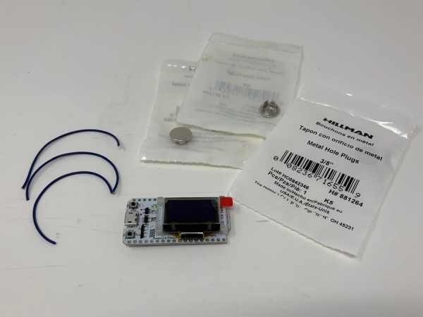
The design utilizes the following hardware:
- One, WiFi Kit 32.
- Three, 3/8″ metallic hole plugs.
- Three, 4″ lengths of 28awg wire.
To assemble the hardware, I performed the following steps:
- Stripped and tinned the ends of each 4″ wire length as shown.
- Soldered the first wire to pin 13 of the ESP32 (the TOUCH4, or “T4”, input).
- Soldered the second wire to pin 12 of the ESP32 (the TOUCH5, or “T5”, input).
- Soldered the third wire to pin 14 of the ESP32 (the TOUCH6, or “T6” input).
- Soldered one of each of the three 3/8″ metallic hole plugs to the free ends of the three wire lengths.
Step 2: Software.
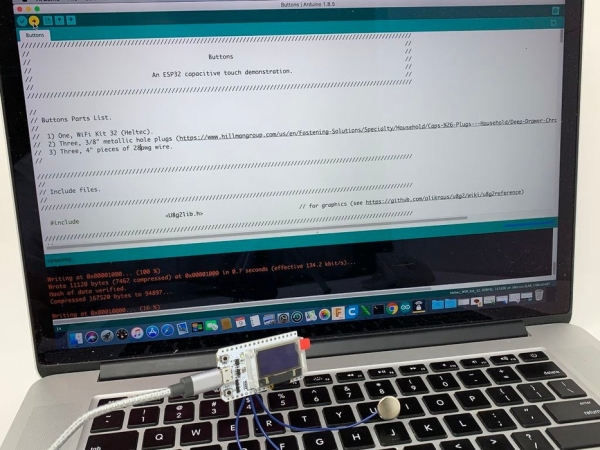
The file “Buttons.ino” is an Arduino environment file containing the software for the design. In addition to this file, you will need the “U8g2lib” graphics library for the WiFi Kit32 OLED display (see https://github.com/olikraus/u8g2/wiki for further information on this library).
With the U8g2lib graphics library installed in your Arduino directory, and “Buttons.ino” loaded into the Arduino environment, compile and download the software into the ESP32.
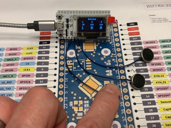
Once downloaded and running, the top line of the display should read “Buttons” with the second line of the display reading “1 2 3” as the button indicators. Below each of the 1, 2, 3 button indicators are the unfiltered touch read values, and below each of these are the button press indicators (“1” for pressed, “0” for not pressed). As can be seen in the video (and as long term tested confirmed), the software filter provides reliable button input detection with no false triggering.
Step 3: About the Software.
The software contains three main code sections; the Arduino required “setup()” and “loop()” sections, and an “Interrupts” section. The setup() section contains the code necessary to initialize OLED and interrupt services. The OLED setup functions are described in the link above. The interrupt service setup functions are as follows:
- “timerLoopSemaphore = xSemaphoreCreateBinary()” creates a semaphore for “InterruptService()” (the interrupt service routine) to inform loop() when it is time to execute a loop pass.
- “timerInterruptService = timerBegin(0, 80, true)” creates a timer using hardware timer 0 with a prescale of 80.
- “timerAttachInterrupt(timerInterruptService, & InterruptService, true)” attaches InterruptService() to the timer.
- “timerAlarmWrite(timerInterruptService, 1000, true)” sets the interrupt service rate to 1000hz.
- “timerAlarmEnable(timerInterruptService)” starts the timer alarm, and thus interrupt service.
With setup complete, loop() is entered and immediately stops at the line:
if(xSemaphoreTake(timerLoopSemaphore, portMAX_DELAY) == pdTRUE),
meaning loop() will wait at this point until the semaphore from InterruptService() arrives. When the semaphore arrives, the loop() code executes, updating the OLED display with the button data, then returning to the top to again awaiting the next semaphore. With InterruptService() running at 1000hz and a LOOP_DELAY value of 30, loop() executes every 30ms, or at a display update rate of 33.333hz. While this is a higher display refresh rate than required for most ESP32 applications, I used this setting to illustrate the responsiveness of the filter. I did test and determined the time required to execute a single loop() pass to be 20ms.
InterruptService() is called by the timer created in setup() at a rate of 1000hz. When called, it updates two down counters, nLoopDelay and nButtonDelay. When nLoopDelay is down counted down to zero, it sends the semaphore allowing loop() to execute a single pass then resets nLoopDelay. When nButtonDelay is down counted down to zero, it too is reset then the button “filters” execute.
Each button filter has a unique filter counter (e.g. nButton1Count, nButton2Count and nButton3Count). As long as the touch input value assigned to the button is greater than or equal to the defined threshold value (BUTTON_THRESHHOLD), the filter counter assigned to the button and the button remain zero. If the touch input value assigned to the button is less than the defined threshold, the filter counter assigned to the button is incremented by one every 20ms. When the filter counter exceeds the button filter value (BUTTON_FILTER), the button is considered “pressed”. The effect of this method is to create a filter requiring 80ms (20ms nButtonDelay * 4ms nButtonCountN where N is the button number) of continuous touch input values below the defined threshold to consider the button actually pressed. Any time less than 80ms is considered a “glitch” and is rejected by the filter.
Given this brief description, if you have any questions, please feel free to ask and I will do my best to answer them.
Hope you enjoyed it!
Step 4: The “Upcoming Project”.
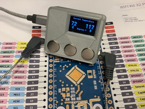
The upcoming project, “Intelligrill® Pro”, is a dual temperature probe smoker monitor featuring:
- Steinhart-Hart temperature probe calculations (as opposed to “look-up” tables) for increased accuracy.
- Predictive time to completion on probe 1 incorporating the increased accuracy derived from the Steinhart-Hart calculations.
- A second probe, probe 2, for monitoring smoker temperature (limited to 32 through 399 degrees).
- Capacitive touch input controls (as in this Instructable).
- WIFI based remote monitoring (with a fixed IP address, enables monitoring of the smoker progress from anywhere an internet connection is available).
- Extended temperature range (again 32 through 399 degrees).
- Audible completion alarms both within the Intelligrill® transmitter and on most WiFi capable monitoring devices.
- Temperature display in either degrees F or degrees C.
- Time format in either HH:MM:SS or HH:MM.
- Battery display in either volts or % charged.
- And coming soon, PID output for auger based smokers.
“Intelligrill® Pro” is testing to become the most accurate, feature packed and reliable HTML based Intelligrill® I have designed.
It’s still under test, but with the meals it’s assisting to prepare during testing, I’ve gained more than a few pounds.
Again, I hope you enjoy it!
Step 5: Next Up: ESP32 NTP Temperature Probe Analog Input With Steinhart-Hart Correction
Be prepared to dust off your algebra books for this one.
Source: ESP32 Capacitive Touch Input Using “Metallic Hole Plugs” for Buttons