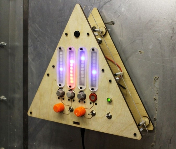
What’s that smell? It’s noxious gas of course! If you’re in an environment where there’s a possibility of gaseous release of which you’d rather not breathe, why not build an automatic system for sensing and alerting you? The design for the Environmental Alert System is driven by my motivation to understand the concentrations of different chemicals in the air. The unit consists of an array of four gas sensors (one each for methane, propane, carbon monoxide, and smoke) connected to an Intel Edison for wireless detection and alerting. While no substitute for a proper commercial chemical detection system, the EAS makes for a great weekend project!
Update: I wrote a guide to making electronics project boxes, which you might find useful if you’ve not got your own laser cutter and want to make an enclosure for your environmental alert system.
Step 1: Parts and Materials
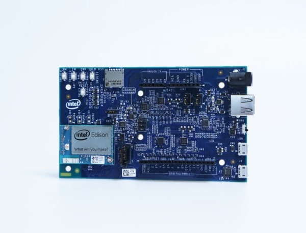
Intel Edison with Arduino Breakout Board
(4x) 10K rotary panel-mount potentiometer
(4x) 1/4″ slot knob
MQ-2 (flammable gas and smoke)
MQ-4 (methane)
MQ-6 (propane)
MQ-7 (carbon monoxide)
(4x) gas sensor breakout
(3x) 20K resistor
10K resistor
1K resistor
330 ohm resistor
panel-mount LED holder
5mm green LED
5V buzzer
2N3904 NPN transistor
1/4″ plywood
1/8″ acrylic
(12x) 1″ 4-40 standoff
(24x) 1/2″ 4-40 screw
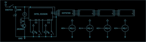
Step 2: Electrical Design
Power
The entire system is powered from a 5V 3A power supply. Each of the four sensors draws upwards of 150 mA, the Edison around 500 mA, and the DotStar LEDs (at full white brightness) up to 2400 mA. Since the DotStar strip will never be fully on or set to white, the 3 amp supply should work just fine. The entire system is switched on via a mini toggle switch. A single green LED is connected via a 330 ohm resistor to the 5V rail to show the power status.
Control
An Intel Edison runs the show for the Environmental Alert System. The Edison is mounted on an Arduino breakout board, which makes it easy to read the analog signals from the sensors and potentiometers. The Edison is connected to the 5V rail via a micro usb cable. The Edison has a built-in Wi-Fi radio, which allows it to connect to the internet without the need for any additional hardware.
Sensors
The system has four sensors that connect the Edison. Each sensor is directly powered from the 5V rail and has its signal pin connected respectively to A0 through A3 on the Edison breakout board. The sensors also each have a sensitivity adjustment resistor; the MQ-7 has a 10K ohm resistor and the rest each have a 20K resistor. The MQ-2 is a combustible gas sensor (liquified petroleum gas, propane, hydrogen, and methane) that outputs an analog voltage proportional to the concentration from 300 to 10,000 parts per million. The MQ-4 is a methane gas sensor and has a equivalent concentration to voltage response. The MQ-6 is an LPG, isobutane, propane sensor. The MQ-7 is a carbon-monoxide sensor.
User Input
There are two potentiometers and two toggle switches for user input. The toggle switches are connected between the digital pins on the Edison (pulled high via software) and allow selection between the two “threshold” adjustment potentiometers. The potentiometers are connected across the 5V rail and have their wipers connected to the remaining analog inputs on the Edison (A4 and A5).
User Feedback
The Edison connects and controls a single strip of DotStar LEDs via SPI. Each strip is cut into four segments of 10 LEDs each and then connected in series to form a single strip, which makes for simpler software control. The system also has a buzzer for immediate auditory feedback if any of the sensors detects a value above the set threshold. The buzzer is connected to 5V and is controlled via a single NPN transistor that is driven by one of the Edison’s GPIO pins.
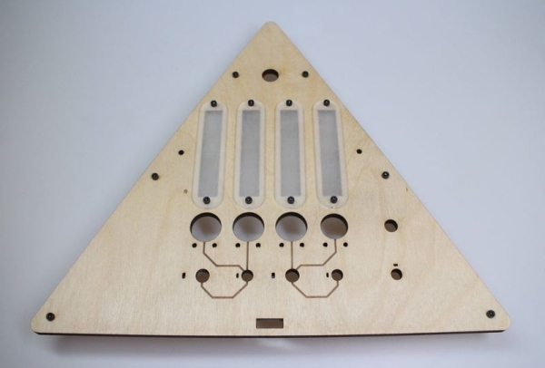
Step 3: Mechanical Design
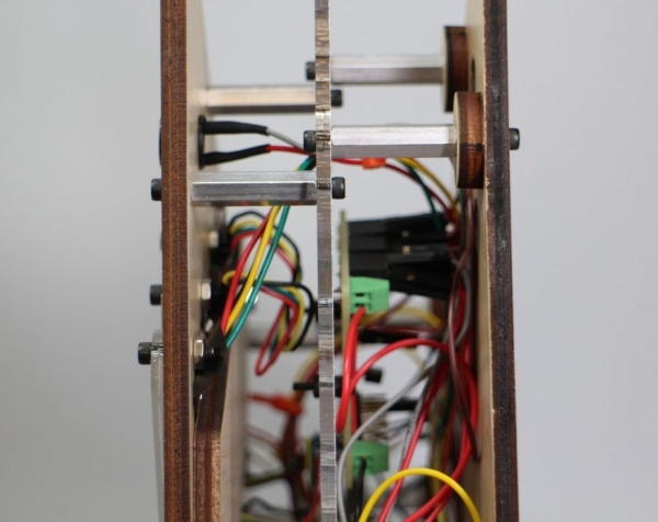
The body of the E.A.S. is made out of three plates of laser-cut sheets. Although I used a combination of 1/4″ plywood and clear acrylic, the design can be assembled out of any sheet material as the spacing (maintained by 1″ aluminum standoffs) is the only critical element. The clear window plates in front of the LEDs are optional, but allow for some much needed light diffusion. I designed the frame in a triangular shape reminiscent of many danger and warning signs. I’ve attached the vector files for download above.
Step 4: Electronic Assembly
Power
The power for the system is provided by a beefy wall-wart with a standard barrel jack which is connected directly to the power switch. The barrel jack must be screwed into its plate prior to soldering. The ground wire is connected to a terminal block on the mini protoboard. The output of the switch is connected via 22 AWG wire to the adjacent hole on the terminal block. There are male and and female headers on either side of the proto board to allow quick power connections.
Sensors
The sensors are attached to breakout boards (they can be soldered in any orientation) on one side, with male headers and the resistors on the other; this configuration allows the sensors to be mounted “flush” with the front of the face plate. The sensors connect to the Edison via male-to-female jumper wires.
Output
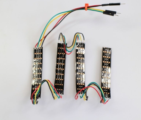
The buzzer is broken out with female header wires to allow for quick assembly. The driver transistor and gate resistor are soldered on the mini protoboard with a single male header attached to the collector of the transistor. The LED strips are broken into four 10 LED segments and reconnected with four wires between each. The tiny copper pads on the LEDs are especially difficult to solder, so extra care must be taken in order to attach them properly. The LED strip is broken out with male header wires.
Step 5: Frame Assembly: Face
Faceplate
Potentiometers – simply pop into place and are secured with their matching nuts. The optional knobs fit snugly on top and are fastened with set screws.
Switches – pop into place with the groove facing towards the top. The lockwasher remains below, while the nut and tabbed-washer for each fastens the switch to the plate and aligns them vertically.
Buzzer – slides into the topmost large hole and is held with a friction fit.
Sensors – fit into their matching holes and are secured with two nylon 2-56 screws each.
LED – pops into the hole above the power switch and is fasten with its matching nut.
Step 6: Frame Assembly: Middle
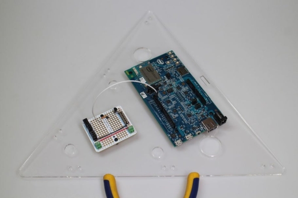
Midplate
Barrel Jack – screws into its mini plate with its matching nut Standoffs – are attached with six 1/2″ X 4-40 screws Edison – is fastened with four 2-56 screws and eight nuts (half immediately underneath and the rest on the other side of the plate
Read more: Environmental Alert System