Once the purview of strictly military operations, GPS has become a regular part of modern living and in relatively short time! Who wouldn’t want want to know when and where they are anywhere on the planet? It’s a science fiction dream brought into reality, one now so woven into our lives it seems almost trivial. The demand for precise positional data built into planes, ships, cars, and now nearly every modern cellular phone means a few things for the average hobbyist: smaller, higher quality, lower cost, easier to use, and better documented GPS receivers available for purchase!
In this Instructable, we’ll discuss the Global Positioning System as a whole and build a simple circuit for communicating with a receiver with the Intel Edison. This setup will allow us access to positional data, which will open the possibility for more advanced interpretation and enable real-world applications.
Step 1: What Is GPS?
Brief History
The roots of the Global Positioning System go back to the height of the Cold War when advancing space technology was a high priority for the American government. While initially conceived for providing a strategic military advantage for the U.S. war machine and (among other things) the need to precisely guide Intercontinental Ballistic Missiles toward their far off targets, it was eventually opened up to civilian use in the 90s (albeit at an intentionally degraded precision for non-military receivers). Eventually the full accuracy afforded by the satellites was opened to the public in spring of 2000.
The System as we use it today is fairly modern network, with true global coverage only coming online within the middle of the last decade. It is not the only satellite system capable of providing positional data however, the Russian GLONASS also came online within a similar time frame as the GPS. Due to political and financial constraints, adoption of GLONASS receivers has been less prevalent. The EU, China, Japan, and India are also developing similar satellite networks of regional use, although GLONASS is the only comparable network of global coverage.
How Does it Work?
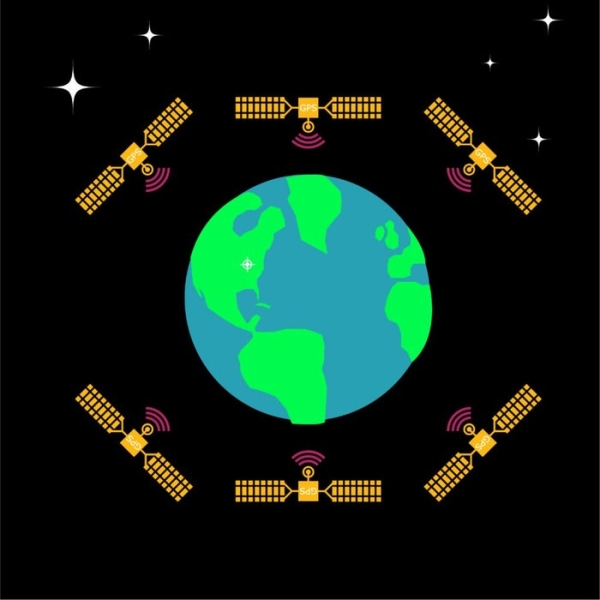
Each satellite has a stable atomic clock on board for broadcasting accurate time data. Each satellite continuously broadcasts its time position data which can then be processed by a receiver. A receiver must have at least four satellites in range to have an accurate “lock” on its location (three points of data for location, and one for time reference). The actual work of the receiver boils down to computing the signal delays of the transmissions and converting this into easy-to-use data for the user. This is, of course, a vast simplification of the system; the reality of the inner workings of GPS are quite complex and very impressive. Thankfully, it is quite easy and of low cost to interface with a basic receiver from an end user’s standpoint.
Step 2: GPS Modules
Due to the intense market demand, there are a wide variety of GPS receivers available from many manufactures, often coming as an all-in-one shielded package alongside a basic ceramic antenna. Which module is right for your next electronic project? Here are some things to consider when choosing which to buy:
Choosing the Right Receiver
Power Considerations:
Like most modern electronic components, GPS receiver modules are following the standard of running on ever lower voltages with 3.3V being most common. Most projects will only be receiving data, making 3.3V and acceptable voltage for a logic high bit to your 3.3 or 5V system. Many receivers allow a modest amount of configuration depending on how you’d prefer the module to transmit its packets, so be aware of the system voltage. A single 1K resistor on your 5V processor’s Tx line to the module’s Rx line should be sufficient. Most receivers are also quite power efficient, usually drawing well below 100 mAh and often in the sub 50 mAh range during steady reception, making them practical for most battery powered designs.
Antenna:
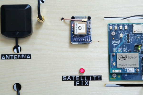
Many common modules and breakout boards often come with a built-in ceramic patch antenna. These tiny beige-ish blocks with a conductive blob in their centers are sufficient for most GPS reception projects, especially if you’re wanting compact size. Some modules come with pre-soldered SMA or wee u.fl connectors on board for connection to an external antenna, which is especially useful if you wish to mount your receiver inside a hard case.
Update Rate:
Normally you’ll find modules with a 1 Hz update rate, providing a sufficiently steady stream of data for most slow moving projects. Newer modules also offer 5 Hz or 10 Hz+ data rates, but this is really only useful for fast moving projects like quadrotors zipping around a course. An update rate in excess of 1 Hz is also potentially overwhelming for smaller micros with minimal amounts of RAM.
Bonus Features:
Some modules include a built-in super capacitor or battery for backup power during power cycling, allowing for a faster time-to-first-fix. The MTK3339 module I’m using also has a small data-logging capability, which is interesting for a brief recording experiment, but less useful for long term data collection and storage.
Simple Connection Circuit:
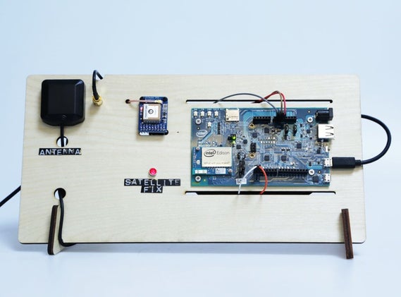
I’ll be discussing the actual data we’re receiving from the GPS module on the following steps. For my own testing purposes, I’ll be using Adafruit’s Ultimate GPS breakout board and an Intel Edison with the Arduino Breakout. The board will accept either 3.3 or 5 volts as power, and has handy standard 2.54mm pinout for attaching to a breadboard or female jumper wires. As you can see from the simple connection diagram above, I’m only connect three pins on the module: power to 5 volts, ground to ground, and the module’s Tx line to the Rx of the Edison’s UART, which is broken out to pin 0 on the Arduino board. It’s as easy at that! There are other pins broken out for configuring the module, checking the satellite lock, power control, and a steady pulse output, but the single Tx to Rx connection is all you’ll need to begin receiving GPS data.
GPS Receiver Links:
Here is the exact module that I’m using from Adafruit. Sparkfun and Seeedstudio also offer a selection of different receivers as well.
Step 3: Deciphering NMEA Protocols
How Are We Receiving Data?
Most receivers you come across will transmit informal over a simple serial data connection. Often it is encoded in plain ASCII characters, but there are other compact binary formats available from some modules for higher data rates. We’ll be looking at a regular ASCII feed since it is much easier to interpret.The data we’re receiving from the GPS module is formatted according to NMEA 0183 standard.
The NMEA Protocol
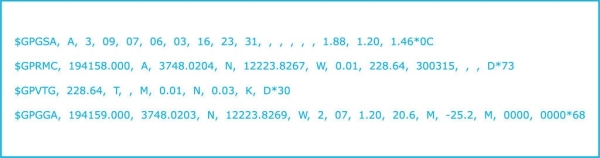
The National Marine Electronics Association has a standard for many different ship-board electrical devices. The NMEA 0183 standard is useful for GPS receivers to output since it is a clear, and relatively slow (typically 4800 or 9600 baud) protocol that is palatable for any modern microcontroller with a UART to handle. Let’s look at a sample block of four string output by the MTK3339 module. I’ve spaced out the string above to make it clearer to read, but the raw stream has no spaces after commas and a single set of carriage return and line feed characters at the end of each string (strings begin with a “$” character).
GPGSA
Global Positioning Active Satellites – This string will tell us the number of satellites that are currently in range of the module, the type of fix (2D or 3D) and the precision of the signal.
GPRMC
Global Positioning Recommended Minimum Coordinates – This is the meat of the data strings, containing the time of fix, if the receiver is ok, latitude, longitude, speed (in knots), fix type.
GPVTG
Global Positioning Course Over Ground (Track Good) – This contains more data regarding ground speed in knots and kilometers per hour.
GPGGA
Global Positioning System Fix Data – full coordinate data containing everything in the RMC string, in addition to extra accuracy data as well as altitude. We’ll break this string down more thoroughly on the next step.
Read more: Intro to GPS With Microcontrollers