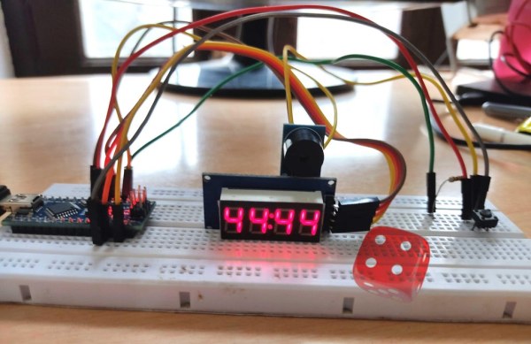
The electronic dice presented here, built around a tiny Arduino Nano board, mimics the dice we play in different games like snake and ladders the most popular. Plastic and wooden dice are subject to wear and tear with time and might show biasing toward a specific number defying theory of randomness and the player as well. As this dice is completely electronic and programmed with zero bias this makes it an idle to rely on. It has a bright red light display and cheers sound when a player gets the highest number 6 of his best luck. So, let us play a new game today!
Step 1: Get Required Parts
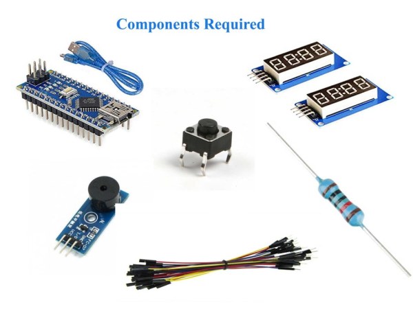
We have used Arduino Nano if you are a professional or electronics enthusiast you will have it or else buy it online with a few little bucks. We are not using a 7-segment display as it requires lots of wires and resistors moreover it waste board pins that could be used connecting some other device. I have found out four-pin 7-segment display TM1637, it has four 7-segment displays and one colon. One Buzzer, a Tactile Switch, a Resistor, and few connecting wires would complete our bill of materials. Last but not least one laptop pc installed with Arduino IDE.
List of Components
- Arduino Nano
- TM1637 7-Seven Segment Display
- An active Buzzer
- A Micro-Switch
- 10K Ohm Resistor
- Connecting Wires
Step 2: TM1637 4-Digits 7-Segment Display
As already said a bare 7-segment display uses more wires and add-on resistors also. If we interface a 4-digit 7-segment display it would require 12 wire connections, plus resistors and transistors as well. This means tons of wiring and wastage of pins that could be used connecting any other device.
The TM1637 reduces pin connections just to four. Two pins are used for power connections, supply, and ground, and the other two for clock and data input-output. So, we are saving 8-pins!
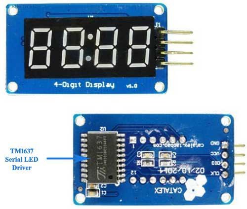
At the heart of the module is an inexpensive serial LED driver from TitanMicroelectronics TM1637. Thus the display prefix this chip name and called TM1637 7-segment display.
The TM1637 supports many functions, like ON/OFF and brightness control of the LEDs as well as accessing each of the segments. You can also adjust the LED brightness at the software level.
The TM1637 module includes four 0.36 segment 7-segment displays to display data.
The TM1637 module operates on a supply voltage of 3.3 to 5 volts and communicates over a two-wire bus, so it only requires two data pins plus supply and ground, a total of four pins only.
Pinout
- CLK – clock input pin to the display – used for data input-output at the rising edge
- DIO – data input-output pin – used for serial data input and output
- VDD – positive power supply – connected to 3.3V to 5V
- GND – ground pin – connected to ground
Step 3: TM1637 Library Installation
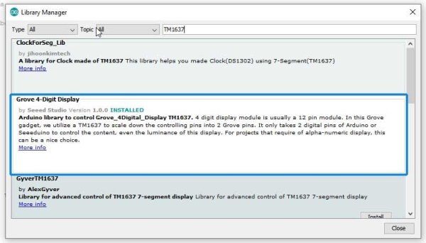
To work TM1637 7-segment display with Arduino nano you need to install its library. In the “Manage Library” search box type “TM1637” and install “Grove 4-Digit Display” by seed studio, as you see can see in the image for help.
Step 4: Make Connections
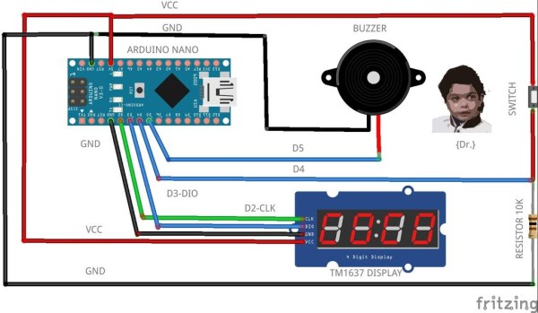
I have used digital pins D2, D3 Display, D4 connected to the tactile switch, and D5 to the buzzer.
Here below are the connections :
- D2->Display CLK
- D3->Display DIO
- D4->Switch
- D5->Buzzer
- GND->GND
- VCC->VCC
Step 5: Programming
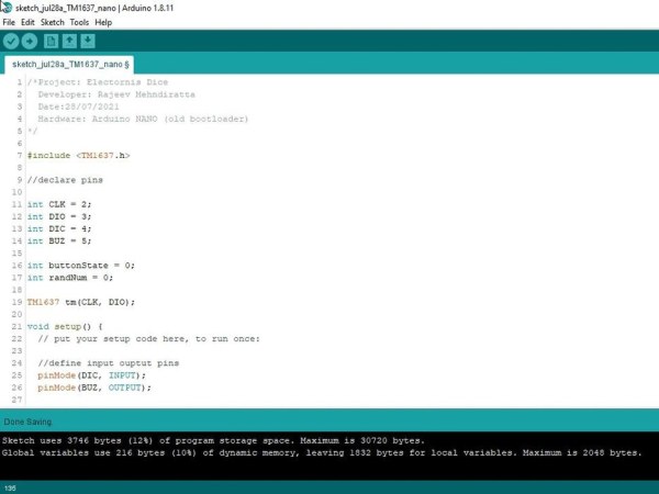
Understanding the Code
Include TM1637 library header file:
#include <TM1637.h>
Pins and variables declarations:
int CLK = 2;
int DIO = 3;
int DIC = 4;
int BUZ = 5;

int buttonState = 0;
int randNum = 0;
Define input and output pins:
pinMode(DIC, INPUT);
  pinMode(BUZ, OUTPUT);
Initialize serial communication at 9600bps:
Serial.begin(9600);
Define state of pins low or high:
digitalWrite(DIC, LOW);
  digitalWrite(BUZ, HIGH);
Initialize TM1637 display:
tm.init();
Set display brightness level:
tm.set(2);tm.init();
Read whether the switch has been pressed or not:
buttonState = digitalRead(DIC);
If the switch is pressed, HIGH, call throwDice function and send it to serial monitor for debugging:
randNum = throwDice();
Serial.println(randNum);
Display the respective digit using the Switch Case statement:
switch (randNum) {
      case 1:
        tm.display(0, 1);
        tm.display(1, 1);
        tm.point(1);
        tm.display(2, 1);
        tm.display(3, 1);
        delay(5000);
        randNum = 0;
        break;
      case 2:
        tm.display(0, 2);
        tm.display(1, 2);
        tm.point(1);
        tm.display(2, 2);
        tm.display(3, 2);
        delay(5000);
        randNum = 0;
        break;
      case 3:
        tm.display(0, 3);
        tm.display(1, 3);
        tm.point(1);
        tm.display(2, 3);
        tm.display(3, 3);
        delay(5000);
        randNum = 0;
        break;
      case 4:
        tm.display(0, 4);
        tm.display(1, 4);
        tm.point(1);
        tm.display(2, 4);
        tm.display(3, 4);
        delay(5000);
        randNum = 0;
        break;
      case 5:
        tm.display(0, 5);
        tm.display(1, 5);
        tm.point(1);
        tm.display(2, 5);
        tm.display(3, 5);
        delay(5000);
        randNum = 0;
        break;
If the random number is 6 drive buzzer:
<pre>case 6:
        tm.display(0, 6);
        tm.display(1, 6);
        tm.point(1);
        tm.display(2, 6);
        tm.display(3, 6);
        digitalWrite(BUZ, LOW);
        delay(5000);
        digitalWrite(BUZ, HIGH);
        randNum = 0;
        break;
Reset button state and random number:
buttonState = 0;
randNum = 0;
Else if the switch is not pressed continue to display 0:
else
  {

    tm.display(0, 0);
    tm.display(1, 0);
    tm.point(1);
    tm.display(2, 0);
    tm.display(3, 0);

    buttonState = 0;
    randNum = 0;
  }
Function throwDice uses an inbuilt random() function to generate random numbers between 1 and 6:
int numRand = random(1, 7);
Return random number generated to the caller:
return numRand;
Complete Code
upload it on your Arduino Nano board
/*Project: Electornis Dice
  Developer: Rajeev Mehndiratta
  Date:28/07/2021
  Hardware: Arduino NANO (old bootloader)
*/

#include <TM1637.h>

//declare pins

int CLK = 2;
int DIO = 3;
int DIC = 4;
int BUZ = 5;

int buttonState = 0;
int randNum = 0;

TM1637 tm(CLK, DIO);

void setup() {
  // put your setup code here, to run once:

  //define input ouptut pins
  pinMode(DIC, INPUT);
  pinMode(BUZ, OUTPUT);

  //initialize serial comm @ 9600
  Serial.begin(9600);

  //define state of pins
  digitalWrite(DIC, LOW);
  digitalWrite(BUZ, HIGH);

  //initializes the pseudo-random number generator
  randomSeed(analogRead(0));

  //initialize TM1637 seven segment display
  tm.init();

  //set brightness; 0-7
  tm.set(2);tm.init();
}


void loop() {
  // put your main code here, to run repeatedly:

  //read button
  buttonState = digitalRead(DIC);

  //decision taking
  if (buttonState == HIGH)
  {
    randNum = throwDice();    //call thowDice function
    Serial.println(randNum);  //serial print for debugging

    //switch case
    // tm.display(position, character);
    switch (randNum) {
      case 1:
        tm.display(0, 1);
        tm.display(1, 1);
        tm.point(1);
        tm.display(2, 1);
        tm.display(3, 1);
        delay(5000);
        randNum = 0;
        break;
      case 2:
        tm.display(0, 2);
        tm.display(1, 2);
        tm.point(1);
        tm.display(2, 2);
        tm.display(3, 2);
        delay(5000);
        randNum = 0;
        break;
      case 3:
        tm.display(0, 3);
        tm.display(1, 3);
        tm.point(1);
        tm.display(2, 3);
        tm.display(3, 3);
        delay(5000);
        randNum = 0;
        break;
      case 4:
        tm.display(0, 4);
        tm.display(1, 4);
        tm.point(1);
        tm.display(2, 4);
        tm.display(3, 4);
        delay(5000);
        randNum = 0;
        break;
      case 5:
        tm.display(0, 5);
        tm.display(1, 5);
        tm.point(1);
        tm.display(2, 5);
        tm.display(3, 5);
        delay(5000);
        randNum = 0;
        break;
      case 6:
        tm.display(0, 6);
        tm.display(1, 6);
        tm.point(1);
        tm.display(2, 6);
        tm.display(3, 6);
        digitalWrite(BUZ, LOW);
        delay(5000);
        digitalWrite(BUZ, HIGH);
        randNum = 0;
        break;
    }
    buttonState = 0;  //rule out false triggering
    randNum = 0;      //clear last digit

  }

  //waits for swith to be pressed

  else
  {

    tm.display(0, 0);
    tm.display(1, 0);
    tm.point(1);
    tm.display(2, 0);
    tm.display(3, 0);

    buttonState = 0;
    randNum = 0;
  }

}

//function to generate randowm number

int throwDice() {

  int numRand = random(1, 7);   // min=1 and max= max-1, 6
  return numRand;
}
Source: Electronic Dice With Arduino Nano