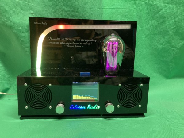
Summary of EDISON Radio
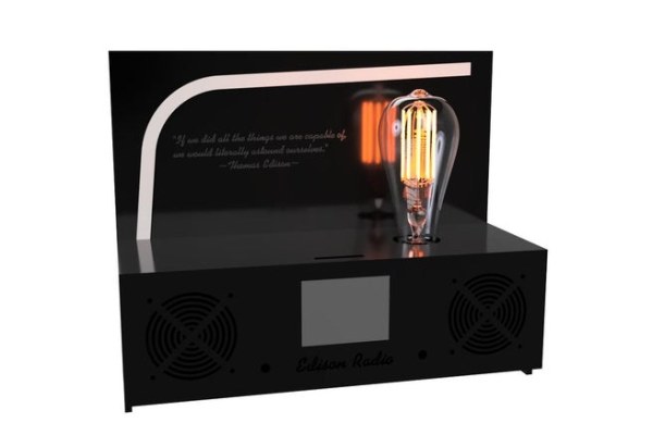
The Edison Radio is an internet radio project based on Ed Smallenburg's ESP32 design. This build features a search engine for stations by country, station logos on the browser interface, a TFT spectrum analyzer, LED VU meter, and audio sliders. The project emphasizes a custom housing with a modified decorative LED light bulb as a centerpiece. Assembly requires soldering skills, an Arduino IDE, and specific tools like a laser cutter for acrylic panels.
Parts used in the Edison Radio:
- ESP32 DEVKIT 1.0
- PCB Set
- Potmeter 50K or similar
- Display (TFT Screen)
- Rotary Encoder
- IR receiver
- WS2812B Pixel LEDs
- Modified decorative LED light bulb (E27 Titanium Rustic Lamp)
- Acrylic plates (5mm for housing, 1mm for cover)
- Audio transformers
- Soldering station
- Laser cutter service
- Power supply and speakers
This project is bases on the internet radio by Ed Smallenburg. He did an awesome job in creating a working internet-based radio. He shared his coding and hardware on the world wide web so that people like you and me can learn from it. He shared his build on GitHub using the copyleft license. (It basically comes down to: use it, modify it as needed, don’t copyright it and share….)
You can find Ed’s original build and data here:
https://github.com/Edzelf/ESP32-Radio
So, I started with Ed’s Arduino sketch and I added a few extra options:
- Search engine to find Internet Radio station by country.
- Find and implement the station’s Logo and display it on the browser interface.
- Spectrum analyser on the TFT Screen
- LED VU meter with Pixel leds WS2812
- Sliders for changing Audio Settings.
The modified software and all project data will be available here:
https://github.com/donnersm/EdisonRadio
TIP: download all with one click by pressing the green button and choosing “download ZIP”
As you might have noticed, this project is named the Edison Radio. Thomas Edison was a great inventor who, amongst other things, improved the microphone for telephones by developing a carbon microphone. In ways, more than one, Edison contributed to worldwide communication. However, his greatest invention was not this carbon microphone or even his well-known phonograph but, it was the invention of the light bulb by far! Without Edison, we might still be using candles to bring light in darkness. That is why this radio has a light bulb as centrepiece. .. O yeah, this 100% optional attribute also looks kind of cool
TOOLS NEEDED
You will be working with low voltage (5V max) but you should know your way around basic electronics. Using the wrong voltage or polarity might kill your project in an instance!
Being successful in building this device requires some adequate skills and tools. You should be able to solder small components on a PCB which will require a soldering station with a small tip as you will be handling components like 0805 sized and a LQFP-48 package. If this is beyond your possibilities, then you should ask someone to do it for you or order an already assembled PCB.
(Availability will depend on demand).
Furthermore, you be programming the microcontroller by using the Arduino IDE environment. Although the steps to do so will be described in this document, it is advisable for you to get to know this Arduino software.
If you are considering building the Edison housing, you will need to produce the panels for it. It can be done by hand, but it would be best to use a Laser cutter. Remember, there are some companies that offer a laser cutting service. Maybe there is a company near you who can do it for you?
And yes, you will need some basic tools like a screwdriver
Supplies
PCB set: PCB Set
Acryllic plate 5mm to make the panels for the housing ( or design and build to your own liking)
ESP32 DEVKIT 1.0 DEVKIT
Potmeter 50K or simular
Optional:
Display
Rotary Encoder
IR receiver
And you’ll need a power supply and some speakers
To give this radio more of an “Edison” look I decided to implement the optical illusion of a Edison Light Bulb. It is optional and without it, the radio will function just fine. However, this ornament justifies the name of this radio. Doesn’t it? You can leave it out but, you will be missing out on this very cool looking tribute to the world’s best inventor.
The light bulb is actually a modified decorative LED light. ( Edison Light Bulb) The one I bought is from CALEX holland and is called the E27 Titanium Rustic Lamp art. 473894
There are several models available and you might have to adjust your wiring and voltage supply if you decide to buy a different light bulb.
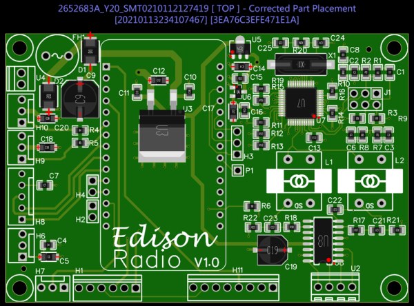
Step 1: Main PCB
The pcb without components is available at my Tindie store here:
Shipping is only possible within the EU because shipping to other countries will involve import Tax, declarations of conformity and other complicated stuff. Nobody is looking for that kind of complicated formalities or import tax upon receiving the goods. If you are a resident of a country that I don’t ship to, you can always order a pcb directly from a PCB supplier near you. The Gerber productions files you need for that are available for download, although it might be more expensive than what you are hoping for. If you need 1 or 2 PCB’s, a Tindie order is the cheapest way to go.
Depending on demand….I might over pre assembled PCB’s. Keep an eye on my Tindie store.
Assembly notes:
- Assembly of the bottom side are not that difficult all the only components on the bottom are 100nf smd 0805 capacitors (C26,27,28,29,31,32,34)
- Make sure you have the orientation of specific components correct. Resistors and ceramic capacitors are not critical but Electrolytic capacitors and semiconductors have to go on the right way! Do not mix up Cathode and Anode.
- The audio transformers L! and L2 also have an orientation. Make sure to align the letters ‘SD’ or dot, with the silkscreen of the PCB. WARNING, I encountered several versions that had this marking on the wrong side of the transformer. This makes it hard to tell which side is primary and which side is secondary. Best is to try it. If you solder everything else first, you can connect a speaker and play some music. You can then simply try what way to mount the transformers. Or use a socket so it is easy to reverse when necessary. When mounted correctly, a clear sound will be what you hear but if it is reversed, all you will hear is digital noise.
- I Used MOLEX connectors and headers but you can use any type you like if it fits the PCB. The raster used is 2.54″
- Connectors H2, H4, H3 and P1 can be left out. Those are connected to the unused pins of the ESP32 board in case I need them later for experimenting and debugging.
- Use a socket for the fuse and for the ESP32. A socket makes swopping them a lot easier.
- In my experience, it works best to assemble U7 and U8 before the rest. U7 might be the most difficult of the whole PCB and you will need a steady hand as well as experience in soldering SMD components. Safe all the connectors for last.
Full documentation like schematic, assembly drawing etc. is available at my Github:
https://github.com/donnersm/EdisonRadio
Here are some links for some of the used components. A more detailed list of components is available on one of the following pages of this document.
ESP32 controller
https://nl.aliexpress.com/item/4000152270368.html?spm=a2g0s.9042311.0.0.1ec64c4ddCHl0d
Audio transformer
https://nl.aliexpress.com/item/32913784557.html?spm=a2g0s.9042311.0.0.27424c4d6fwORq
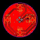
Step 2: Light Bulb Modification
To give this radio more of an “Edison” look I decided to implement the optical illusion of a Edison Light Bulb. It is optional and without it, the radio will function just fine. However, this ornament justifies the name of this radio. Doesn’t it? You can leave it out but, you will be missing out on this very cool looking tribute to the world’s best inventor.
The light bulb is actually a modified decorative LED light. ( Edison Light Bulb) The one I bought is from CALEX holland and is called the E27 Titanium Rustic Lamp art. 473894
https://www.partsnl.nl/led-glasfiber-titanium-st64-rustieklamp-35w-e27-dimbaar-473894
There are several models available and you might have to adjust your wiring and voltage supply if you decide to buy a different light bulb.
The one I bought was surprisingly easy to modify to my needs. Basically, you can unscrew the outer glass and take out the inner part and socket. I then pulled out the inner cylinder from it’s socket by force and removed the LED PCB from the socket. I then saw off the lower part (lamp foot)and re-attached the cylinder to the socket so that it screws back into the outer glass bulb. So, this leaves me with the outer light bulb and the inner cylinder in place. The only difference is that now, the bottom of the cylinder is open and I can attach a small PCB with pixel LEDS to it.
Basically, this PCB only contains 4 pixel LEDS WS2812B and an optional connector or wire input. You can look at it as a ledstrip of 4 LEDS that you can connect serially with the Logo ledstrip. The LEDS can be purchased here:
Make sure you place those LEDS in the correct orientation. There is a marked corner on the silkscreen for each LED that must match with the marking on the LED’s. The light bulb PCB will be connected to the WS2812B-LED Strip that is used with the Logo. If you don’t use the logo, you can connect the light bulb PCB directly to the main PCB logo Ledstrip connector.
Step 3: Making the Parts for the Housing
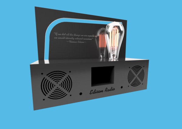
Although I might not be completely neutral in this matter, I believe that this ‘EDISON’ Design is very cool and elegant looking…..Wouldn’t you want one? If you do, feel free to download the AutoCAD files to ‘laser cut’ or mechanically engineer your own. It is fine if you prefer to modify that design or use your own creation instead but know that me design is freely available.
I used a laser cutter to cut all the acrylic parts (5mm thickness) for this casing. The space that is to be filled with the VU meter has a plastic cover made of 1mm transparent or ‘milk’ acrylic that is glued into place. Using a milky colour will defuse the light to look more elegant fluent. You can experiment with different colours of (semi) transparent cut out acrylic to find whatever gives you the best vibe.
All the parts of the casing are glued together using proper glue for the used materials.
Except for the bottom plate what is hold in place by two small screws.
Step 4: Putting It All Together
When you have all the components and parts, you can start the assembly.
Casing
The bottom panel is the only panel that is hold in place by two screws. All other panels are glued into place with acrylic glue. I used Acrifix(1R0192) but your local store might have something similar.
The first step is to glue the backplate of the ledstrip onto the back panel. You can also mount the LCD protection glass if you decide to use it. You will have to experiment with the size because it depends on the size of your cutters’ laser beam. I designed mine to be 0,5mm larger in width and height to compensate for it. That way it will fit in place perfectly.
Tip: To assemble and glue everything together, a solid 90° angle will help. I use a metal profile and some clamps as support.
- First, I glued the front top and sides together.
- I mounted the display, speakers, potmeter, rotary switch, power switch and power entry.
- I started wiring as much as possible.
- I mounted the main PCB to the bottom plate.
- I glued the whole assembly to the backplate.
- I connected the wires to the PCB.
- This would be the time to program your ESP32.
- Test It!
- Close it up by attaching the bottom plate with two little screws.
- I had no use for operating switches or IR receiver. But, you can implement it if you like.
Step 5: Wiring It All Up
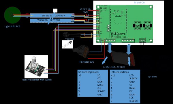
The wiring is not that spectacular. The internal wire to connect the power input to the main PCb should be thick enough to handle about 3A. The Gnd and power wire to the LEDStrips should be able to handle 1A. The rest is not that big of a deal. However, I did twist the speaker wires by channel. It’s an old habbit. The rest of the wires I bound together using some straps like T-Raps. Just follow the wiring diagram.
Step 6: Programming
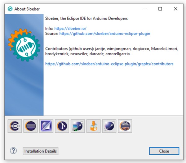
I used the Arduino IDE. It is freely available online and it does the job. However, I recently stumbled on something called Sloeber Beryllium which is a great tool that offers a much better compiler interface. However, it has a bit of a learning curve but I promise, it’s worth it! Why don’t you check it out? You can also use Visual Studio or some other great IDE. However, it is important to install the right library and it is best not to install what you don’t need as it might give you errors when compiling.
Here a few libraries that you’ll need for sure:
- C:\Users\chord\Documents\Arduino\libraries\PubSubClient
- C:\Users\chord\AppData\Local\Arduino15\packages\esp32\hardware\esp32\1.0.4\libraries\SD
- Using library Adafruit_NeoPixel at version 1.7.0 in folder: C:\Users\chord\Documents\Arduino\libraries\Adafruit_NeoPixel
- Using library PubSubClient at version 2.6 in folder: C:\Users\chord\Documents\Arduino\libraries\PubSubClient
- Using library WiFi at version 1.0 in folder: C:\Users\chord\AppData\Local\Arduino15\packages\esp32\hardware\esp32\1.0.4\libraries\WiFi
- Using library ESPmDNS at version 1.0 in folder: C:\Users\chord\AppData\Local\Arduino15\packages\esp32\hardware\esp32\1.0.4\libraries\ESPmDNS
- Using library SPI at version 1.0 in folder: C:\Users\chord\AppData\Local\Arduino15\packages\esp32\hardware\esp32\1.0.4\libraries\SPI
- Using library ArduinoOTA at version 1.0 in folder: C:\Users\chord\AppData\Local\Arduino15\packages\esp32\hardware\esp32\1.0.4\libraries\ArduinoOTA
- Using library Update at version 1.0 in folder: C:\Users\chord\AppData\Local\Arduino15\packages\esp32\hardware\esp32\1.0.4\libraries\Update
- Using library Ethernet at version 2.0.0 in folder: C:\Program Files (x86)\Arduino\libraries\Ethernet
- Using library Adafruit_ILI9341 at version 1.5.6 in folder: C:\Users\chord\Documents\Arduino\libraries\Adafruit_ILI9341
- Using library Adafruit_GFX_Library at version 1.10.4 in folder: C:\Users\chord\Documents\Arduino\libraries\Adafruit_GFX_Library
- Using library FS at version 1.0 in folder: C:\Users\chord\AppData\Local\Arduino15\packages\esp32\hardware\esp32\1.0.4\libraries\FS
- Using library SD at version 1.0.5 in folder: C:\Users\chord\AppData\Local\Arduino15\packages\esp32\hardware\esp32\1.0.4\libraries\SD
- Using library Adafruit_BusIO at version 1.7.1 in folder: C:\Users\chord\Documents\Arduino\libraries\Adafruit_BusIO
- Using library Wire at version 1.0.1 in folder: C:\Users\chord\AppData\Local\Arduino15\packages\esp32\hardware\esp32\1.0.4\libraries\Wire
Remark: I had some trouble compiling when I started. Turned out that Arduino IDE had many libraries activated and it decided to choose the wrong ones whenever it had to choose between libraries. I solved it by uninstalling the Arduino IDE and re-installing it from scratch.
Preparing the ESP32 to use the NVS
WARNING: DO NOT SKIP THIS STEP IF YOU WANT A FUNCTIONAL RADIO
If you start by running the main program without running this little tool first, you will find yourself a radio that doesn’t work. It won’t start because it cannot find the table with settings that is stored in NVS, causing it to reboot…and.. reboot…and reboot…
So your first step should be to run the initialization tool. It is called Esp32_radio_init and you can find it in the project folder on GITHUB
https://github.com/donnersm/EdisonRadio/tree/main/ArduinoSketch/InitializeTool
You need to run it at least once. Do not worry about the content it puts in the NVS, you can change that later in the main program.
To run it, open the “Esp32_radio_init.ino” with your Arduino IDE ( of your own software if you prefer), upload it and start…You can monitor what it is doing by using your serial monitor.
Uploading the main program
The main program can be downloaded from GITHUB here:
https://github.com/donnersm/EdisonRadio/tree/main/ArduinoSketch/MainProgram
Open it with your Arduino IDE, compile and upload. If you used the same configuration as I did, then it should work without trouble. However, If you used a different display or you want to activate some of the disabled features, you’ll need to adjust the code accordingly. If you can’t get the information on how to do that from this document, I would suggest to check out the documentation of the original design that was done by Ed Smallenburg. You can find it here:
https://github.com/Edzelf/ESP32-Radio/tree/master/doc
After uploading, there is a big change you will start hearing one of my favourite Jazz stations. Feel free to change them to your likings.
Source: EDISON Radio
- How do I find Internet Radio stations by country?
The modified software includes a search engine feature specifically designed to find stations by country. - Can I use a different light bulb model?
Yes, several models are available, but you may need to adjust your wiring and voltage supply. - Does the project require a laser cutter?
No, it can be done by hand, but using a laser cutter is recommended for producing the acrylic panels. - What is the best way to assemble the PCB components?
It is best to assemble U7 and U8 before the rest and use a socket for the fuse and ESP32 to make swapping easier. - How do I fix the reboot loop issue after uploading code?
You must run the Esp32_radio_init tool first to initialize the NVS settings before uploading the main program. - Can I omit the light bulb ornament?
Yes, the radio will function just fine without the light bulb, though it is optional. - What libraries are required for programming?
Required libraries include PubSubClient, SD, Adafruit_NeoPixel, WiFi, ESPmDNS, SPI, ArduinoOTA, Update, Ethernet, Adafruit_ILI9341, Adafruit_GFX_Library, FS, Adafruit_BusIO, and Wire. - Is shipping available for the PCB set outside the EU?
Shipping is only possible within the EU; residents of other countries should order directly from a local PCB supplier.