
Summary of A DIY laser engraver build using DVD and CD-ROM/writer
Summary (under 100 words): A DIY laser engraver built from two salvaged CD/DVD drive assemblies: one provides X/Y stepper motors and the other supplies a red laser diode. An ATmega328p running grbl firmware controls two EasyDriver stepper drivers and a LM358-based adjustable laser driver. The usable engraving area is about 38 mm × 38 mm. Configuration uses grbl settings for steps/mm, acceleration, and homing; g-code is generated with Inkscape plus an engraver extension and sent via Grbl Controller or similar. Safety warnings about Class IIIb laser hazards are emphasized.
Parts used in the DIY laser engraver:
- CD-ROM writer assembly (for one axis motor)
- DVD-ROM writer assembly (for laser diode and other axis motor)
- Red laser diode (from DVD-ROM optics, ~100 mA)
- LM358 based adjustable laser driver (with TTL enable)
- Alternate: LM317 based laser driver (optional)
- Two small stepper motors (from CD/DVD drives)
- Two EasyDriver stepper driver boards (Allegro A3967 based)
- ATmega328p microcontroller (Arduino Mini used)
- Power supply for motors (5 V)
- Wiring, connectors, and mechanical frame to mount assemblies
- Inkscape with laser engraver extension (software)
- Grbl Controller or Universal-G-Code-Sender (host software)
To build this tool I’ve used two old CD-ROM writer that lays around in my garage.
The X/Y positioning system it is build using the CD-ROM motor assembly. For the engraving laser i use the CD-ROM writer laser.
In CD-ROM and DVD-ROM you could also find IR driver, DVD laser writer diode will be a little more powerfull than the CD one.
Laser diode usually has three pins, one is the common ground, laser and photodiode cathode (-), one the laser diode anode (+), the other is the monitor photodiode anode(+).
If the diode you are using has no mark, and you do not know the diode pinout, you have to find the laser cathode and anode. One simple method I use is to power up the diode with a 1.8 to 2.2v current, just for a little amount of time, let’s say 1s, if it sucks current, that wiring is the laser diode pinout.
Once again, if you do not know the motors wiring, you have just have to pay attention to pair each coil and then connect to the EasyDriver motor output. If direction is inverted, invert the coil wiring, or just setup grbl to invert the axis direction.
I’m using grbl version grbl v0.8c (ATmega328p, 16mhz, 9600).
You just have to upload the firmware using your favorite uploader, the grbl wiki page drive you on how to do this step.
On the grbl wiki page you could also find any other information about command and software setup.
Commands to the engraving machine are sent through UART.
When you assembly your harware, pay attention to build it making X normal to the Y axis. The two direction has to be perpendicular, or your engraving will has distorsion.
Below you should find the schematics i’m using.

Below you can find the grbl configuration parameters i changed, basically what i’ve changed here is:
Set step/mm to setup the correct motor distance to run (a common step/mm value for CD-ROM motor should 53.333):
$0=53.333 (x, step/mm)
$1=53.333 (y, step/mm)
Set the accelleration value to 100:
$8=100.000 (acceleration, mm/sec^2)
Enabled the homing cycle:
$17=1 (homing cycle, bool)
If you need to invert axis direction, “Step port invert mask, int:binary” is the paramenter you have to touch. Those are the most common inversion, but if you need other inversion, look at the grlb wiki for this parameter:
$6=32 (invert x axis)
$6=64 (invert y axis)
$6=96 (invert x and y axis)
To test it, just send the
X10 Y10
command, or use the Grbl Controller rows, you should see a 10mm movement on each axis.
Also check the “spindle on” command power your laser on and off.
Now you could be able to send g-code drawing to your engraver.

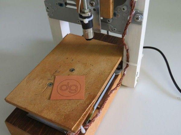
The working are for this plotter is 38mm x 38mm, so setup your project area to this dimension.
Once you have you path, then you could select the path you want to engrave, and transform it using the InkScape laser engraver extension.
Just copy the extension on your extension inkscape folder, restart inkscape, and use that to build your g-code file.
Once you have your g-code file, you could send it to grbl using Grbl Controller, or other software like Universal-G-Code-Sender.
Notes
- read risk disclaimer
- excuse my bad english
- What is the engraving area of this DIY laser engraver?
The engraving area is almost 38 mm x 38 mm. - What laser diode is used in this project?
A red laser diode taken from the DVD-ROM writer optics, rated around 100 mA. - How are the X and Y axes implemented?
The X/Y positioning uses the CD-ROM/DVD-ROM motor assemblies and small stepper motors from those drives. - Which microcontroller and firmware are used?
An ATmega328p running grbl (example: grbl v0.8c at 16 MHz, 9600 baud) is used. - What drivers are used for the stepper motors?
Two EasyDriver stepper driver boards (Allegro A3967 based) are used to drive the motors. - What laser driver is recommended?
The builder used a small LM358 based adjustable driver capable of 10 mA to 400 mA with a TTL enable; an LM317-based driver is an alternative. - How do you determine unknown diode or motor pinouts?
For a diode, briefly apply 1.8–2.2 V for about 1 second and see which wiring draws current; for motors, identify coil pairs and connect to EasyDriver outputs, then invert wiring or configure grbl if needed. - Which software is used to create and send g-code?
Inkscape with a laser engraver extension is used to generate g-code; Grbl Controller or Universal-G-Code-Sender is used to send commands to grbl. - What grbl settings were changed for this setup?
Steps/mm set to 53.333 for X and Y ($0 and $1), acceleration ($8) set to 100.000 mm/sec^2, and homing enabled ($17=1); axis inversion uses $6 bitmask if needed. - How do you test movement and laser control?
Send a command like X10 Y10 to move 10 mm on each axis; use spindle on/off commands to power the laser.