Update: 7th April 2019 – Rev 3 of lp_BLE_TempHumidity, adds Date/Time plots, Using pfodApp V3.0.362+, and auto throttling when sending data, alongside Low Power BLE in Arduino Update: 24th March 2019 – Rev 2 of lp_BLE_TempHumidity, adds more plot options and i2c_ClearBus, adds GT832E_01 support
Introduction
This tutorial, A Redbear Nano V2 Replacement, is Part 3 of 3. This is Revision 2 of this project. Revision 2 PCB includes mounting for the coin cell and the sensor, simplifies construction and improves air flow around the sensor while shielding it from direct sunlight. Revision 1 is here.
Part 1 – Building Very Low Power BLE devices made Easy with Arduino covers settting up Arduino to code nRF52 low power devices, the programming module and measuring the supply current. It also covers specialized low power timers and comparators and debounced inputs and using pfodApp to connect to and control the nRF52 device.
Part 2 – A Very Low Power Temperature Humidity Monitor covers using a Redbear Nano V2 module and an Si7021 temperature/humidity sensor to build a low power battery / solar monitor. It also covers modifying the Si7021 library to be low power, tuning the BLE device to reduce its current consumption to <29uA and designing a custom temperature/humidity display for your mobile.
Part 3 – A Redbear Nano V2 Replacement, this one, covers using other nRF52 based modules instead of the Nano V2. It covers selecting supply components, construction, removing the nRF52 chip programming protection, using NFC pins as normal GPIO, and defining a new nRF52 board in Arduino.
This instructable is a practical application of Part 1 Building Very Low Power BLE devices made Easy with Arduino by constructing a Very Low Power BLE Temperature and Humidity Monitor using a SKYLAB SBK369 board as a Nano V2 replacement. This tutorial covers how to create a new board definition and how to remove the nRF52 programming protect to allow it to be re-programmed. This tutorial uses the same sketch as Part 2 with the same tuned BLE parameters for low power consumption and can be powered from battery OR battery + solar OR solar only. The tuning of BLE parameters for low power was covered in Part 2
Rev 3 of lp_BLE_TempHumidity plots the data against date and time using just the Arduino millis(). See Arduino Date and Time using millis() and pfodApp using the latest version of pfodApp (V3.0.362+).
Rev 4 of pfod_lp_nrf52.zip also supports the GT832E_01 module and this tutorial covers using the NFC nRF52 pins as standard GPIO’s.
The monitor constructed here will run for years on Coin Cell or 2 x AAA batteries, even longer with solar assist. As well as displaying the current temperature and humidity, the monitor stores the last 36 Hrs of 10min readings and the last 10 days of hourly readings. These can be charted on the your Android mobile and the values saved to a log file. No Android Programming is required, pfodApp handles all of that. The Android display and charting is completely controlled by your Arduino sketch so you can customize it as required.
Part 2 used a Redbear Nano V2 board for the nRF52832 BLE component. This project replaces that with a cheaper SKYLAB SKB369 board. As in Part 2, a Sparkfun Si7021 breakout board is used for the Temperature / Humidity Sensor. A modified low power library is used with the Si7021.
Step 1: Why a Nano V2 Replacement?
i) The Nano V2 was out of production for a number of months and does not seem to fit into the Particle.io line up so it is not clear how long it will be available for.
ii) The Nano V2 is more expensive. However it also has extra features. See below.
iii) The Nano V2 has components on both sides which gives it a higher profile and makes it more difficult to mount.
iv) The Nano V2 has limited I/O pins available and using D6 to D10 requires flying leads.
Although the Nano V2 board is more expensive then the SKYLAB SKB369 board, ~US17 versus ~US5, the Nano V2 does have more features. The Nano V2 includes a 3.3V regulator and supply capacitors, extra components for using the nRF52 DC/DC converter option, a chip antenna and a uFL SMT antenna connector.
Another alternative is the GT832E_01 module used by www.homesmartmesh.com. Rev 4 of pfod_lp_nrf52.zip also support programming the GT832E_01 module. The SKYLAB SKB369 and the GT832E_01 are available from https://www.aliexpress.com
Redbear (Particle.io) also has a bare module without 3V3 regulator, DC/DC components or 32Khz crystal components.
Outline
This project has 4 relative independent parts:-
Component Selection and Construction
Removing the nRF52 coding protection flag and programming the sketch
Creating a New Arduino nRF52 Board Definition
Reconfiguring nRF52 NFC pins as GPIO’s
Step 2: Component Selection and Construction
Component Selection
In addition to the nRF52832 and Si7021 components selected in Part 2, this project adds a 3.3V regulator and supply capacitors.
The Voltage Regulator component
The regulator used here is MC87LC33-NRT. It can handle up to 12V inputs and has a quiescent current of <3.6uA, typically 1.1uA. The Nano V2 used a TLV704 regulator has a slightly higher quiesent current, typically 3.4uA and can handle higher input voltages, up to 24V. The MC87LC33-NRT was chosen instead because its datasheet specifies how it responds as the input voltage falls below 3.3V where as the TLV704 datasheet does not.
The TLV704 specifies an input voltage of 2.5V minimum and it is not clear from the datasheet what will happen below that. The nRF52832 will run down to 1.7V and the Si7023 will run down to 1.9V. The MC87LC33-NRT on the other hand specifies input/output voltage differences down to 0V for low currents (Fig 18 of the datasheet). So given the choice of components, the MC87LC33-NRT was chosen because it has the specified performance.
Supply Capacitors
The MC87LC33-NRT regulator needs some supply capacitors for stability and response. An output capacitor > 0.1uF is recommended on the datasheet. The SKYLAB SBK369 also specifies 10uF/0.1uF capacitors on the supply close to the board. Larger capacitors assist in supplying the nRF52 TX current spikes. Here 4 x 22uF 25V and 3 x 0.1uF 50V Ceramic capacitors were used. One 22uF and a 0.1uF capacitor was placed close the the SKYLAB SBK369, a 0.1uF was placed close to the output of the MC87LC33-NRT to ensure stability and a 22uF and 0.1uF were placed on the input to the MC87LC33-NRT and a further 2 x 22uF capacitors where soldered across the Vin/GND pins as a further current reservoir. For comparison the NanoV2 board has a 22uF / 0.1uF on the input to the TLV704 regulator and a 0.1uF on its output.
The extra current reservoir capacitors were installed on the input to the 3.3V regulator so that they would charge to a higher voltage when running with solar cells. Charging to higher voltage equates to storing more current to supply the Tx spikes.
Ceramic X5R capacitors are used because they have low series resistance and low leakage current. The resistance is typically 100,000MΩ or 1000MΩ – µF which ever is less. So for 22uF we have 22000MΩ, i.e. 0.15nA leakage at 3.3V or 0.6nA for the four 22uF capacitors. That is negligible. For comparison Low ESR, Low Leakage Panasonic Electrolytic capacitors have leakage currents of <0.01CV. So for a 22uF 16V capacitor the leakage is <10uA. Note: This is the leakage at the rated voltage, 16V in this case. The leakage is lower at lower voltages, i.e. <2.2uA at 3.3V.
Parts List
Approximate cost per unit as at Dec 2018, ~US$61, excluding shipping and the programmer from Part 1
- SKYLAB SKB369 ~US$5 eg Aliexpress
- Sparkfun Si7021 breakout board ~US$8
- 2 x 53mm x 30mm 0.15W 5V solar cells e.g. Overfly ~US$1.10
- 1 x PCB SKYLAB_TempHumiditySensor_R2.zip ~US$25 for 5 off www.pcbcart.com
- 1 x MC78LC33 3.3V regulator, e.g. Digikey MC78LC33NTRGOSCT-ND ~US$1
- 2 x 0.1uF 50V ceramic C1608X5R1H104K080A e.g. Digikey 445-7456-1-ND ~US$0.3
- 4 x 22uF 16V ceramic GRM21BR61C226ME44L e.g. Digikey 490-10747-1-ND ~US$2
- 1 x BAT54CW, e.g. Digikey 497-12749-1-ND ~US$0.5
- 1 x 470R 0.5W 1% resistor e.g. Digikey 541-470TCT-ND ~US$0.25
- 1 x 10V 1W zener SMAZ10-13-F e.g. Digikey SMAZ10-FDICT-ND ~US$0.5
- 3mm x 12mm nylon screws, e.g. Jaycar HP0140 ~AUD$3
- 3mm x 12mm nylon nuts, e.g. Jaycar HP0146 ~AUD$3
- Scotch Permanent Mounting Tape Cat 4010 e.g. from Amazon ~US$6.6
- CR2032 battery holder, e.g. HU2032-LF ~US$1.5
- CR2032 battery ~US$1
- Perspex sheet, 3.5mm and 8mm
- pfodApp ~US$10
- Solder Paste e.g. Jaycar NS-3046 ~AUD$13
Step 3: Construction
The project is constructed on a small PCB. The PCB was manufactured by pcbcart.com from these Gerber files, SKYLAB_TempHumiditySensor_R2.zip The PCB mimics the Nano V2 pin out and is general purpose enough to be used for other BLE projects.
This is the schematic (pdf version)
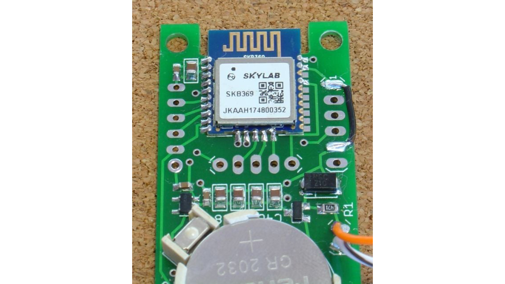
First solder the SMD components, then mount the SKYLAB SKB369 board
Almost all the components are surface mount devices (SMD). The capacitors and IC’s can be difficult to solder by hand. The suggested method is to hold the PCB in a vice and apply a small amount of solder paste to the pads and place the SMD components, except for the SKB369 board on the PCB. Then using a heat gun, apply heat to the underside of the PCB until the solder paste melts and then do a quick pass over the top of the board being careful not to blow the components off. Finally touch up the components with a small tip soldering iron. Be careful with the capacitors and resistor as it is easy to melt both ends and have the component come loose while soldering one end.
This revision add extra 22uF 16V ceramic capacitors. These extra capacitors reduce the current spikes drawn from the battery and also the reduce the voltage dips when being powered from the solar cells. As long as the voltage from the solar cells remains above the battery voltage then no current is drawn from the battery.
After the SMD components have been mounted, you can solder in the SKYLAB SKB369 board. There are two test point holes on one side of the SKB369 tabs. Use two pins into a cardboard base to position the SKB369 board and carefully align the pins. (See the example photo above using the Revision 1 PCB) Then solder one pin of the opposite side to hold the board in place before soldering the other pins.
Note the Gnd link wire from the CLK to GND in the finished part. This is installed AFTER programming to prevent noise on the CLK input from triggering the nRF52 chip into a high current debug mode.
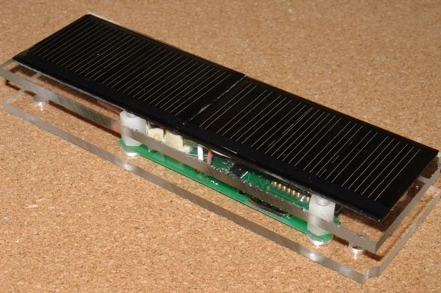
Mounting Case
The mounting case was made from two pieces of perspex, 110mm x 35mm, 3mm thick. The 3.5mm piece under the solar cells was tapped to take the 3mm nylon screws. This revised construction is simplifier then Rev 1 and improves air flow around the sensor. The extra holes at each end are for mounting, using cable ties for example.
Source: Easy Very Low Power BLE in Arduino Part 3 – Nano V2 Replacement – Rev 3