Summary of Easy 4×6 LED Matrix, Arduino!
This Instructable guides hobbyists with basic Arduino skills on building a 4x6 LED matrix. It details the necessary hardware, explains the column-row addressing mechanism using transistors and resistors, and introduces Persistence of Vision (POV) to create animations. The project includes an animation creator tool in Step 4 to help users design custom light patterns by rapidly blinking rows.
Parts used in the 4x6 LED Matrix:
- An arduino board
- Twenty-four LEDs of the same color
- Four transistors
- Four 100ohm resistors
- Four 1Kohm resistors
- A fair amount of wire
- Animation creator program
In this inst’able, I will show you how to create your very own 4×6
LED matrix as well as show you how to write code for it!
There is an animation creator program in step 4!
Here is one ANIMATION to get you excited about the project!

This Inst’able is for the electronic enthusiast/hobbyists that has basic
knowledge of the simple hardware used, and a good grasp of the
arduino programming language!
Email me at “[email protected]” if you have any questions about
the instructable.
Post Videos of your own LED Matrices!
FOLLOW ME FOR MORE GREAT INSTRUCTABLES!!
Step 1: Hardware
For this project you will need:
- An arduino board;
- Twenty-four LEDs of the same color;
- Four transistors;
- Four 100ohm resistors;
- Four 1Kohm resistors;
- And a fair amount of wire.
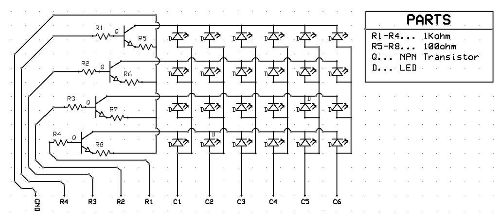
“C” stands for Column while “R” stands for Row.
Columns are vertical, varying the Y axis
Rows are horizontal, varying the X axis.
Click Here for a bigger and better res. view of the above schematic
How The Hardware Works:
The hardware works by applying +5 volts to the desired column and row, and having GND wired to the arduino’s GND pin. If I apply +5v only to C1, there will be +5v ready to be passed through all of the LEDs in column 1, but still has to go through the transistors in order to get to GND and there are no LEDs on.. On the other hand, if I apply +5v only to R1, that transistor will allow current to pass from any LED in row 1 to GND. But since there is no voltage applied to any of the columns, no LED is turned on.
From what I have said thus far, we can see that +5v must be applied to a Column and a Row at the same time for any LED to be turned on. Here is where we run into a problem: the only way to turn on 3 LEDs [(C1, R2), (C1, R1), and (C2, R1,) which are the three lowest and to the left] is to apply +5v to pins R2, R1, C1, and C2. The problem with this is that it will also turn on LED (C2, R2)! See step 2 for how to solve this problem, read on for the technical specs!
Technical stuff…
Schematic Pin Name———–Digital Arduino Pin They Connect To
C1………………………………..9
C2………………………………..8
C3………………………………..7
C4………………………………..6
C5………………………………..5
C6………………………………..4
R1………………………………..10
R2………………………………..11
R3………………………………..12
R4………………………………..13
GND……………………………..GDN Well, duh! = )
Step 2: Persistence Of Vision! (POV)
In step 1–the hardware step–we couldn’t turn on more than one LED. How do we fix this?
The answer to this question lies in our wonderful eyes, and their insistence in persistence.
When lights blink very rapidly, our eyes perceive them as being consistently on. We can use this to our advantage when creating animations. To see how the Matrix uses this, see step 4.
The Animation Creator file included in STEP 4 and is designed to blink each row really fast and can be used by the novice animator to achieve fame and fortune! ok, well, maybe not. but still!
Step 3: Lights, Camera, Lights!
In the above photo are a few snapshots of the Matrix in action!
These are come of the animations I have made.
You can download these animations, as well as
the animation creator that I created for the Matrix!
you will find all of the programs you will need in step 4.
arduino board;
animations
Twenty-four LEDs
For more detail: Easy 4×6 LED Matrix, Arduino!
- Who is this project intended for?
This Instructable is for electronic enthusiasts or hobbyists who have basic knowledge of simple hardware and a good grasp of the Arduino programming language. - What does POV stand for in this context?
POV stands for Persistence of Vision, which allows eyes to perceive rapidly blinking lights as being consistently on to create animations. - How many LEDs are required for the matrix?
The project requires twenty-four LEDs of the same color. - Which digital pins connect to columns C1 through C5?
C1 connects to pin 9, C2 to 8, C3 to 7, C4 to 6, and C5 to 5. - How do you turn on a specific LED in the matrix?
You must apply +5v to both a Column and a Row at the same time for any LED to turn on. - Where can I find the animation creator tool?
The animation creator file is included in Step 4 of the instructions. - What happens if you apply +5v to only one column without a row?
No LED will turn on because the current still needs to pass through the transistors to get to GND via a row voltage. - Can I download existing animations created for this matrix?
Yes, you can download animations made by the author along with the animation creator from Step 4.