Please vote for Drawing Robot on this link.
Thanx in advance
Fixing my drawing incapability with my robotics skills and to me results were not that bad. Now I can at least save my self from humiliation in my drawing class.
This project is good for beginners and gives sufficient exposure to arduino, matlab coding and mechanics. There is not much in the electronics department. The bot is a basic 2DOF arm with a pen manipulator. This project involves application of inverse kinematics and canny edge detection.
Step 1: Parts, Tools and Software Required
1. Mechanical
- Mechanix kit
- Nut and bolts
- Pen Holder (Clothespin)
- 2X Caster wheels
2. Electronics
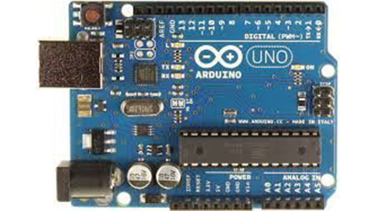
- Arduino uno
- PCB or Bread board
- Power Supply (5V adapter with 2A current)
- USB Cable
3. Servo Motors
4. Tools
- Soldering Iron
- Soldering Wire
- Screw driver
- Drilling Machine
5. Software
- Arduino IDE
- Matlab (with Arduino IO)
Above links are for India, so you can find this stuff with your local retailer easily.
You can take any servos with torque greater than 7Kg.cm and for bread board users soldering iron and wire are not required.
Step 2: Mechanical Design
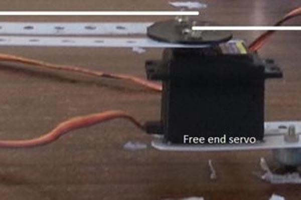
From the pictures above you get the idea of what the design is and how you should go about assembling it. It is more like playing with maker kits when you were 5 or 6 years old. So lets start step by step construction.
- Drill two holes in each of the horns such that the distance between the two holes is same for all the horns as given in the picture.
- Now we have to make a rigid support for one end. Drill four holes at appropriate distances as the screws of the servo and attach the servo to the box. We will use this setup to give a rigid support to the setup.
- Join two combinations of aluminium stripes from the kit to any two horns as shown in the picture such that the distance between the two horns should be ~20 cm.
- Now attach one horn to the servo with rigid support and one to the other servo and before fixing the horns, calibrate the servos to 90 degrees so that rigid servo is parallel to the stripes and the free end servo is perpendicular to it.
- Now take two longest stripes (15 cm) fro the kit and attach them to the lower end of the free end servo parallel with it.
- Then attach caster wheels at the bottom of the arm with the pen which we constructed in step 5 for proper balance and support.
- The last servo should be attached at the end point of the step 5 with feviquick or glue gun anything that makes it rigid there.
- With a stripe of appropriate length and clothespin attach the pen to the servo such that the distance from the free end horn and the pen tip should be ~20cm.
While construction two points should be kept in mind that the distances mentioned above should be 20 cm and calibration should be done properly. Rest of the construction depends on the availability of parts and your wish. For example instead of aluminium stripes from the kit you can use rulers for arms etc.
Step 3: Electronics Part
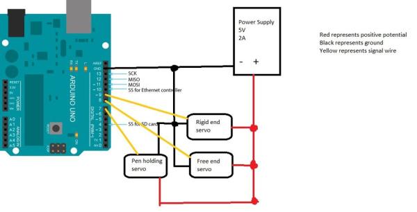
The picture above is self explanatory you can either make a shield for the arduino as I have done or a bread board for the circuit.
Step 4: Coding
This part of the project is the most interesting part and the most important as well.
Let me give you a briefing of what is happening.
First we take an image and find its edges with the help of canny edge detection and we are going to draw this image. Drawing the image has two parts
PART 1: First we find the pixel which is 1 as our image is now in the form of 0s and 1s and then check its local pixels if any one of them is also 1 then the pen reaches that pixel and deletes the previous 1. The function repeats it self recursively and creates smooth lines.
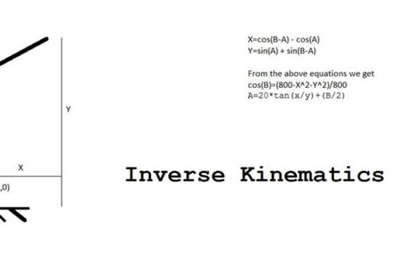
PART 2: The second part involves the inverse kinematics part of how to reach that particular pixel. It simply takes in the coordinates of the pixel and calculates the corresponding angles for the pivots, the calculations are shown in the above picture.
The above explanation is not required for the execution of the code it is just for understanding.
Now how to setup Matlab and arduino for the execution of the code.
First install the arduino IO package on matlab (all the instructions are given with the package).
Now replace the arduino.m file with the file the file that I have uploaded with same name.
Download and save finaldraw.m and draw.m in matlab directory.
Upload the adioes.ino file that I have uploaded to the arduino board.
See to which port your arduino is connected and then go to finaldraw.m and change COM3 to your port.
Change the extension of the image which you want to draw to .png. This can be done in any image editor now save this image to the matlab directory. Open the finaldraw.m and change emma.png to your image name with .png extension.Save the finaldraw.m file.
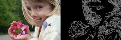
I have uploaded the picture of emma watson as a sample, so you can use it for testing and you can also adjust the parameters of the canny edge detection function according to your need.
We are done now connect the arduino to your PC and switch on the power supply and type finaldraw in matlab command line. HAVE FUN !!!
If you are facing any problems then comment below.
Step 5: Coding Continued……….
The working of the algorithm is very simple, it is just the matter of visualizing how the bot approaches the image drawing.
This is an elaborate explanation and feel free to skip it.
Firstly, I convert the the image that I want to draw in png format using some image editor, then I save the Image in the matlab directory. Now our algorithm converts this image using canny edge detection as given in the image above. The mysterious part is drawing this image.
What the algo does is it starts checking the pixels of the converted image and when it finds 1 which is indicated as the white pixel in the image above, the pen tip reaches that point (The reaching part is covered in the previous step clearly) and puts the pen down then it checks neighboring 8 pixels, if it finds a 1 it reaches that point without lifting the pen up and deletes the previous pixel to avoid repetition. Now this continues till it finds no 1s in the neighborhood(this is a recursive function) hence it draws smooth line deleting it simultaneously. Then it completes other branches of lines that emerge from the drawn line as it checks every neighboring pixel. This algorithm ultimately creates the whole image. Now watch the video given in the beginning again and try to connect the dots you will surely feel a GEEKY MENTAL ORGASM that I felt when I figured this elegant algorithm after a lot of failed attempts. HOPE YOU LIKED MY INSTRUCTABLE IT WAS MY FIRST SO APOLOGIES FOR A ROUGH TUTORIAL!!!!!!!
Source: Drawing Robot