Summary of Drawing on a 7×5 LED matrix with Arduino in C
This article details driving a 7x5 green LED matrix (LTP-7357AG) with an Arduino Uno using C code. The author created a custom library to handle column scanning, limiting active dots to two per subframe to prevent exceeding the ATmega's current limits. The project successfully displays characters like "B" by configuring specific I/O ports and managing timing via delays or interrupts.
Parts used in the LED Matrix Display Project:
- LTP-7357AG 7x5 LED matrix
- Arduino Uno
- ATmega microcontroller
- USB-serial converter
- 220 Ohm resistors
- C programming library (ledmatrix.h)
In my component drawers I have a LTP-7357AG, which is a matrix of 35 green LEDs conveniently packaged in a 12-pin display. I wanted to play with it so I began to hook it with my Arduino Uno. This post is part of a series about programming Arduino applications in C.
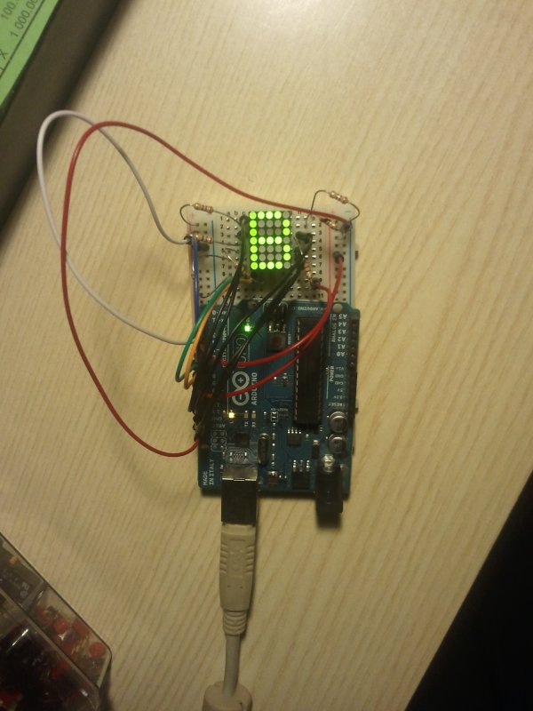
I’m going to show the results first, and then give an explanation of what I did and why. The following image shows that the Arduino is capable of showing a letter on the display.
I made this by writing a library in C that handles the LED matrix when it’s connected to particular I/O ports, and together with the library I wrote a main program that displays the “B”:
#include <util/delay.h>#include "ledmatrix.h" // The header of my library.#define FRAME_RATE_HZ 50 // This feels sufficient#define SUBFRAME_RATE_HZ (FRAME_RATE_HZ * N_SUBFRAMES) // N_SUBFRAMES is in ledmatrix.h#define SUBFRAME_DELAY_US (1000000 / SUBFRAME_RATE_HZ)int main(void){ struct ledmatrix_frame fB = // struct ledmatrix is a 5-bytes struct holding a 7x5 frame. LEDMATRIX_FRAME_INIT( // A helper macro to write frames easily 11110, // This structure contains a "B" 10001, // 1 means LED is on 10001, // 0 means LED is off 11110, // they are transformed into binary numbers by "magic" in LEDMATRIX_FRAME_INIT() 10001, 10001, 11110); ledmatrix_setup(); // Initializes ports and stuff. while(1) { ledmatrix_draw_next_subframe(&fB); // Turns on the LEDs of the next subframe. _delay_us(SUBFRAME_DELAY_US); // This loop+delay might be replaced by a periodic interrupt. } return 0;}This is the internal diagram of the component:
The elemental principle for each dot of the display is that if I drive row 1 high and drive column 1 low, I will light up the dot at coordinates (1,1), and if I drive row 1 low and column 1 low I will keep it off.
In the tutorials that can be found online on how to drive a LED matrix, they usually scan the matrix by row or by column. I decided to scan by column, so I hooked one resistor for each row pin. The LED matrix datasheet indicates that each LED has a forward voltage of 2.1V at the typical operating current of 20mA. Given the 5V output of the Arduino I/O, this suggests to use a resistor of around 145Ohm, but I used 220Ohm resistors because that’s what I had available; the downside is that the LED will be less bright because less current will pass through it, nothing dramatic though.
I wanted to connect the LED matrix pins as orderly as possible in terms of Arduino pin numbers, so I started from pin 0 that corresponds to PORTD0 of the ATmega chip, but I had problems with pins 0 and 1 probably caused by the connection to the USB-serial converter mounted on the Arduino Uno.
This is the final wiring of the Arduino to the component:
Note that the colours of the wires match the photo at the beginning of this post. This is a table that explicitly indicates the connection:
LED matrix  - Arduino
COL1(PIN1)  - PB0(PIN8)
COL2(PIN3)  - PB1(PIN9)
COL3(PIN10) - PB2(PIN10)
COL4(PIN7)  - PB3(PIN11)
COL5(PIN8)  - PB4(PIN12)
ROW1(PIN12) - PB5(PIN13)
ROW2(PIN11) - PD7(PIN7)
ROW3(PIN2)  - PD2(PIN2)
ROW4(PIN9)  - PD3(PIN3)
ROW5(PIN4)  - PD4(PIN4)
ROW6(PIN5)  - PD5(PIN5)
ROW7(PIN6)  - PD6(PIN6)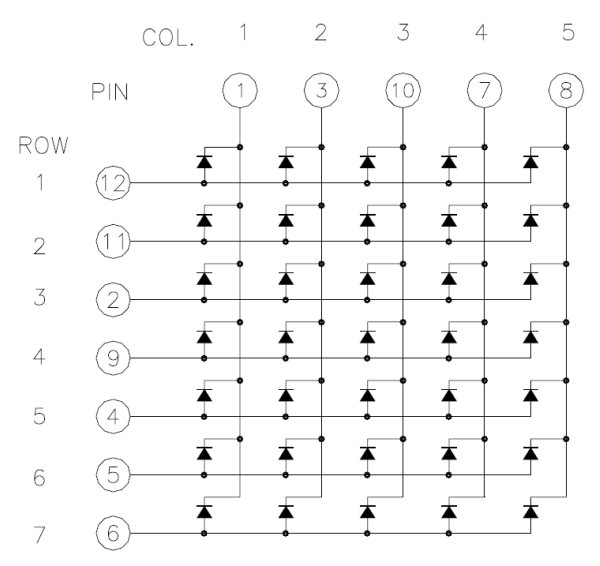
In many examples, when performing a column scan, the active column is driven low by a pin, while the others are not driven: the I/O of the Arduino are configured as high-Z input. In this way one can light up each dot of the column by driving high or low the corresponding pins. The problem with driving 7 dots at once is that the Arduino I/O that keeps the column pin low is sinking too much current: the ATmega datasheet indicates a maximum current of 40mA per pin, but each dot needs roughly 20mA, so we should at most light 2 dots. Some people suggest using a current sink IC to solve this problem, but I don’t have such an IC yet in my inventory, so I decided to consider 2 dots at a time instead of a full column; the dots considered at one time is what is called “subframe” in the code. The following GIF shows the scan of a “B” with a column scan that considers at most 2 dots at a time:
For more detail: Drawing on a 7×5 LED matrix with Arduino in C
- What component is used for the LED matrix?
The LTP-7357AG, a 12-pin display containing a matrix of 35 green LEDs. - Can the Arduino Uno drive all dots in a column simultaneously?
No, doing so would sink too much current; the author limited it to two dots at a time. - Why were 220 Ohm resistors chosen instead of 145 Ohm?
The author used 220 Ohm resistors because they were available, even though 145 Ohm was calculated. - How does the system determine which LED lights up?
An LED lights up when its row is driven high and its column is driven low. - Does the article recommend using a current sink IC?
No, the author decided against using one due to not having such an IC in their inventory. - What problem occurred with pins 0 and 1 on the Arduino?
Problems likely arose due to the connection to the USB-serial converter mounted on the board. - What is the purpose of the SUBFRAME_DELAY_US variable?
It calculates the delay needed between subframes based on the frame rate and number of subframes. - How many rows does the LED matrix have?
The matrix has 7 rows and 5 columns.