Summary of My DIY USB DAC
This article details a DIY USB DAC project using the Texas Instruments PCM2707 IC. The creator designed the schematic and PCB in Eagle, opting for surface-mount components to practice soldering. The device functions as a USB Audio Class 1.0 unit, requiring no drivers on Windows or Mac OS X. Key features include status LEDs, a ferrite bead for noise suppression, and headers for future button controls. The PCB was manufactured by OSH Park, with chips sourced from TI samples and other parts from Digikey.
Parts used in the DIY USB DAC:
- Texas Instruments PCM2707 USB DAC Integrated Circuit
- Indication LEDs
- Ferrite Bead
- Surface mount resistors (0805 size)
- Surface mount capacitors (0805 size)
- PCM2707 component footprint (32-TQFP package)
- SMD USB Mini-B connector
- Through-hole Audio Jack
- Control header pins
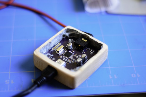
Finished Product!
Here’s the finished DAC! it was a very fun project and very fulfilling to make something that I actually use everyday. Overall the audio specs aren’t anything amazing, but it definitely is an improvement on the built in audio of my computer.
The Schematic
Here is the electrical schematic of the DAC, it uses a Texas Instruments PCM2707 USB DAC Integrated Circuit. It identifies as a USB Audio Class 1.0 device so it doesn’t require any drivers to be downloaded for it to work in Windows and Mac OS X. The circuit is based off of the Application Example in the datasheet from TI, I added a couple indication LEDs to make it easy to tell if the device is powered and connected to a computer. I also added a Ferrite Bead on the USB 5V line to try and suppress any high frequency noise coming across on the 5V line. I created the schematic and PCB layout in Eagle, I’ve been using this program for a while now and it’s pretty easy to throw a board together.
The PCB
After finishing up the schematic, I selected footprints for the parts. I tried to stick with mostly surface mount components since I’ve been trying to work on my soldering skillzzz. Most of the passive components (resistors, capacitors, ferrite beads) are 0805 in size. The PCM2707 is in a 32-TQFP package and I ended up making my own component and footprint in Eagle, I chose to use a SMD USB Mini-B connector and a through-hole Audio Jack since I happened to have these components already and wouldn’t have to order any. The PCM2707 also has the ability to have buttons which control the volume, play/pause, and song skip on the computer it’s connected to. I don’t plan on using these at the moment, but decided to add a header connected to these pins in case I decided on implementing something in the future. After I finished up the PCB, I ordered some from OSH Park (www.oshpark.com), these guys are awesome, I’ve used them for quite a couple of my hobby projects know and the boards are always awesome quality and it only takes a week or two to receive them. I ordered the PCM2707s from TI through their sample program and got the rest of the components through Digikey.
For More Details: My DIY USB DAC
- What integrated circuit does this DAC use?
The project uses a Texas Instruments PCM2707 USB DAC Integrated Circuit. - Does this device require driver installation on Windows or Mac OS X?
No, it identifies as a USB Audio Class 1.0 device so no drivers are required. - Why was a Ferrite Bead added to the circuit?
A Ferrite Bead was placed on the USB 5V line to suppress high frequency noise. - What software was used to create the schematic and PCB layout?
The schematic and PCB layout were created using the program Eagle. - What size are the passive components like resistors and capacitors?
Most passive components are 0805 in size. - Where did the author order the printed circuit boards?
The PCBs were ordered from OSH Park. - How were the PCM2707 chips obtained?
The PCM2707s were obtained through the sample program from TI. - Can the volume and playback buttons be controlled via the board?
The chip supports buttons for volume and playback, though headers were added for potential future implementation.