Summary of DIY Thermal Differential Controller – Part 4: Building Your Own
Summary (under 100 words): This article explains how to build a thermal differential controller based on the author’s redesigned Arduino project. It covers required parts, simple wiring using Arduino connectors (no breadboard needed), and uploading provided Arduino code. Temperature on/off differentials are set via OnDiff and OffDiff variables; an LED indicates load status and optional serial output allows datalogging. The setup controls AC loads via an AC solid state relay but can be adapted for DC loads.
Parts used in the Thermal Differential Controller:
- Arduino (any compatible form)
- 5V power supply (5 to 12V wall wart or cell phone charger)
- AC solid state relay
- LM35 temperature sensors (two)
- 10uf capacitor
- Telephone wire (4 conductor)
In our last episode, I explained how I redesigned the controller from what I first thought I was going to do. Now, I am going to explain how to make your own thermal differential controller based on mine. As it is, this setup will only control an AC load, but it would be fairly simple to convert it to run a DC load.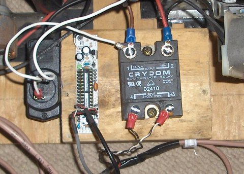
Here is the list of parts you’ll need. I’ve added links to where I like to get parts from.
- Arduino – There are many forms of Arduinos out there. I like the kits from ModernDevice.com since you save some money not having things assembled for you.
- 5V power supply – If you have a spare cell phone charger or wall wart laying around it’ll probably work fine, just make sure its 5 to 12V.
- AC solid state relay – This will keep wiring a bit simpler. You can use a mechanical relay, but you would need to add a diode to protect the Arduino and you might need to add a transistor to help power it.
- LM35 temperature sensors – You’ll need two of these.
- 10uf capacitor – You can probably go with a bit larger or smaller capacitor here. I recommend finding one of similar capacity in some broken electronics component laying around the house if possible. That is what I did. If you have a long wire run to each temperature sensor, you may need a capacitor on both lines.
- Telephone wire (4 conductor) – This will be used for wiring the temperature sensors.
Now that we have all the components, the circuit diagram is quite simple. Since it is so simple, to wire things up, I simply used some connectors on the arduino and ran wires to each component. That way there is no need for a bread board or shield.
Lastly, we need the code for the Arduino. If you haven’t yet, go to the Arduino website and download the Arduino development software. This is required to upload the program to the Arduino. Now, go ahead and download the code for the thermal differential controller.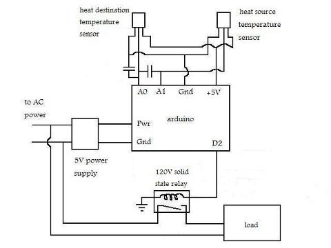
Using the code should be pretty straight forward. I commented pretty throughly. To change the temperature differential to turn the load on, simply plug in a new number into the “int OnDiff =” line. By default its set to 3 degrees Celsius. The differential to control when to turn the load off is controlled likewise by “OffDiff”. There is an LED pin programmed to verify the load on/off status if you want to use it. There is also serial output for the two sensors if you want to uncomment it and datalog the temperatures.
For more detail: DIY Thermal Differential Controller – Part 4: Building Your Own
- What microcontroller is used for the controller?
The controller uses an Arduino (any compatible form). - Can I use a spare phone charger to power the project?
Yes, a spare cell phone charger or wall wart that provides 5 to 12V is suitable. - What type of relay does the article recommend?
An AC solid state relay is recommended to keep wiring simpler. - Which temperature sensors are required?
Two LM35 temperature sensors are used. - Is a breadboard required to wire the components?
No, the author wired components using Arduino connectors and wires, avoiding a breadboard or shield. - How do I change the temperature differential that turns the load on or off?
Edit the int OnDiff and OffDiff lines in the Arduino code to set the on and off temperature differentials. - Is there an indicator for load on/off status?
Yes, an LED pin is programmed to indicate load on/off status. - Can the setup be adapted to control DC loads?
Yes, the article states it would be fairly simple to convert the setup to run a DC load. - Does the code support temperature datalogging?
There is serial output for the two sensors that can be uncommented for datalogging.