
Summary of Daox’s diy arduino thermal differential controller
Summary: A DIY Arduino-based thermal differential controller monitors attic and house temperatures using LM35 sensors and activates a 120V SSR to run vent fans when the attic is about 3°C warmer than the house. It includes a 30-second minimum on-time and optional LED indication; powered by a 5V cell phone charger. Code for analog reading, differential comparison, and relay/LED control is provided.
Parts used in the Thermal Differential Controller:
- Arduino (any compatible board)
- 5V power supply (cell phone charger)
- AC solid state relay (SSR)
- LM35 temperature sensor (x2)
- Telephone wire
- Two bathroom vent fans (example load)
We have a great thread that contains lots of info on thermal differential controllers here. However, I wanted to start a thread dedicated to my own development of a thermal differential controller that I’ll be using for my attic heat reclamation project.
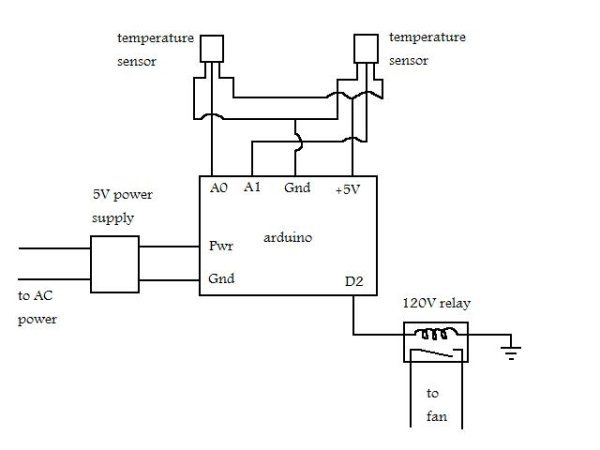
Tonight I setup a simple circuit that tested the operation of the differential controller and it worked great. Its very simple and adding features later on won’t be a big deal at all. I am using the arduino since I know how to use it, its cheap, and it can do everything I’d ever want to be able to do with a thermal differential controller. The temperature sensors are LM35 sensors. They cost a bit more than the thermistors ($1.70 vs $.20) I had planned on using on the controller before, but they are much easier to use while programming and will probably give a better signal over long wire runs. The 120V relay I’m planning on using is a solid state relay (SSR) that the arduino can power directly. The 5V power supply is an old cell phone charger.
As for the operation of the controller, for now its a very simple setup. When the temperature of the attic gets 3C/5.4F higher than the house, the relay kicks on whatever is connected to it. In my case right now, that is two bathroom vent fans. Once the temperature of the attic drops down below the temperature of the house, the relay powers down the fans. There is also a 30 second minimum on time just in case to prevent any odd start/stop situations.
I’m also thinking about adding a LED that indicates that the fans are on, but I’m not sure if that’ll be needed as you’ll probably hear the air rushing out of the vent.
Parts List:
Here is a parts list of what you’ll need. I’ve linked to a few places where I’ve bought things from before.
- Arduino – your choice in what one to use, there are many
- 5V power supply (cell phone charger) – probably have one of these laying around
- AC solid state relay – can use other forms of relay, solid state relays just work well/easy with the Arduino and doesn’t require the diode in the schematic
- (2) LM35 Temperature sensors
- telephone wire – make sure to get enough to put both temperature sensors where you need them
The total for these items comes to ~$40 plus shipping which shouldn’t be too bad. It can definitely be done cheaper if you go with a cheaper arduino or find parts to use.
Arduino program code
/* Thermal Differential Controller
The program monitors two temperature sensors and
activates a relay when one sensor is warmer than
the other.
*/
int SsensorPin = 4; // the pin to input attic temperature
int TsensorPin = 5; // the pin to input kitchen temperature
int RelayPin = 2; // the pin to operate the relay
int ledPin = 13; // led pin (verify fan on condition)
int Ssensor = 0; // variable to store the value of the attic temperature
int SensorDiff = 0; // variable to store the Ssensor value plus differential (Diff)
int Tsensor = 0; // variable to store the value of the kitchen temperature
int Diff = 3.0; // temperature difference that must exist between attic and kitchen before relay enables (degrees C)
void setup() {
pinMode(SsensorPin, INPUT);
pinMode(TsensorPin, INPUT);
pinMode(RelayPin, OUTPUT);
pinMode(ledPin, OUTPUT);
// Serial.begin(9600);
digitalWrite(RelayPin, LOW);
}
 void loop() {
// read sensor inputs and assign to variables
Ssensor = analogRead(SsensorPin) / 2;
Tsensor = analogRead(TsensorPin) / 2;
// add temperature difference to Ssensor value
SensorDiff = Ssensor - Diff;
// send temperature signals back to computer
/*
Serial.print(Ssensor);
Serial.print(", ");
Serial.print(Tsensor);
Serial.print(", ");
Serial.println(SensorDiff);
delay(1000);
*/
// if attic is warmer than kitchen sensor, enable relay
if (SensorDiff > Tsensor && Tsensor < 27) {
digitalWrite(RelayPin, HIGH);
digitalWrite(ledPin, HIGH);
delay(1000);
}
// if attic sensor is cooler than kitchen sensor, disable relay
if (Ssensor < Tsensor || Tsensor > 27 ) {
digitalWrite(RelayPin, LOW);
digitalWrite(ledPin, LOW);
delay(1000);
}
}
void loop() {
// read sensor inputs and assign to variables
Ssensor = analogRead(SsensorPin) / 2;
Tsensor = analogRead(TsensorPin) / 2;
// add temperature difference to Ssensor value
SensorDiff = Ssensor - Diff;
// send temperature signals back to computer
/*
Serial.print(Ssensor);
Serial.print(", ");
Serial.print(Tsensor);
Serial.print(", ");
Serial.println(SensorDiff);
delay(1000);
*/
// if attic is warmer than kitchen sensor, enable relay
if (SensorDiff > Tsensor && Tsensor < 27) {
digitalWrite(RelayPin, HIGH);
digitalWrite(ledPin, HIGH);
delay(1000);
}
// if attic sensor is cooler than kitchen sensor, disable relay
if (Ssensor < Tsensor || Tsensor > 27 ) {
digitalWrite(RelayPin, LOW);
digitalWrite(ledPin, LOW);
delay(1000);
}
}
For more detail: Daox’s diy arduino thermal differential controller
- What microcontroller is used for the thermal differential controller?
An Arduino is used for the project. - What temperature sensors are used?
LM35 temperature sensors are used (two sensors). - How is the relay driven by the Arduino?
An AC solid state relay (SSR) is driven directly by the Arduino. - What triggers the relay to turn on?
The relay turns on when the attic sensor is 3°C higher than the house sensor. - Is there a minimum on time for the relay?
Yes, there is a 30 second minimum on time mentioned to prevent odd start/stop situations. - What power supply is used for the Arduino?
A 5V cell phone charger is used as the power supply. - Why were LM35 sensors chosen over thermistors?
LM35 sensors are easier to use for programming and likely give a better signal over long wire runs despite higher cost. - What load was used in the test setup?
Two bathroom vent fans were connected as the load during testing. - Is an LED included in the design?
An LED is included in the code to indicate fan-on condition, though its physical inclusion is optional. - How much does the parts list cost?
Approximately $40 plus shipping for the listed items.
