Summary of The LCDuino-1 I/O processor
Summary: LCDuino-1 is an Arduino-based, modular LCD driver I/O processor designed as the core of an extensible control framework for audio and other devices. It uses an ATMEGA328P MCU, I²C port expander to drive a standard 2x16 LCD, optional DS1302 RTC and infrared receiver support, and is sized to mate with common LCD modules for compact front-panel mounting.
Parts used in the LCDuino-1:
- Atmel ATMEGA328P microcontroller
- 16MHz ceramic resonator
- MCP23008 I²C port expander
- 2 row x 16 character LCD module (80mm x 36mm, parallel interface, 5V DC)
- LCD mating 6P pin headers (two)
- Backlight (on LCD module)
- Optional DS1302 real-time clock chip
- 32.768KHz crystal for DS1302
- Optional 0.022 Farad supercapacitor for RTC backup
- 3P pin header for Vishay TSOP34838 infrared receiver
- Onboard pushbutton reset switch
- Matching screw holes / enclosure mounting hardware
News
– April 25, 2010: All future announcements and updates for the LCDuino-1 and related app modules (δ1 relay-based attenuator, δ2 relay-based input/output selector, and others) have moved to the new AMB DIY audio forum. We have an entire forum category dedicated to the LCDuino system, with separate sub-forums for each module. LinuxWorks and I will focus our support of these projects there.
Introduction
Ever since I built my β24 power amplifier, I’ve been wanting to build a high-end pre-amp to match. However, rather than using ordinary rotary switches for input/output selection, and a conventional potentiometer or stepped attenuator based on a mechanical switch for volume, I wanted to do something better.
 There are off-the-shelf solutions available for relay-based selectors, relay-based, chip-based or motorized pot volume controls, etc., but virtually all of them are designed for a singular purpose, some are operable with a remote control, some not. Some have a display for status, some don’t. It would be nice to have all of those features, yet implement it in an extensible manner such that more capabilities could be added without wholesale redesign, and to allow a builder to tailor the system to suit his/her exact needs.
Many of you may have noticed the recent Arduino-based LCD driver circuits that linuxworks built on perfboards, controlling a myriad of devices such as the input/output selector and volume control for his β22, a S/PDIF input selector, and even an Espresso machine monitor/controller. Many months ago we began exploring the idea about turning the basic concept into a generic, extensible and modular platform, usable for many applications not only for audio, but other devices too.
Arduino is attractive because of the rich set of tools, libraries, code and support available for firmware development. It uses the C programming language and the GNU C compiler (gcc) in a nice graphical integrated development environment. The environment runs on Linux, Windows and MacOS X. There is also a large and active Arduino programmer and user community where Open Source is de rigeur. In all it’s a very exciting and dynamic scene and fits perfectly with the spirit of our project and goals.
The LCDuino-1
The first result of this collaboration is the LCDuino-1 I/O processor, which will serve as the “heart” of the entire framework.
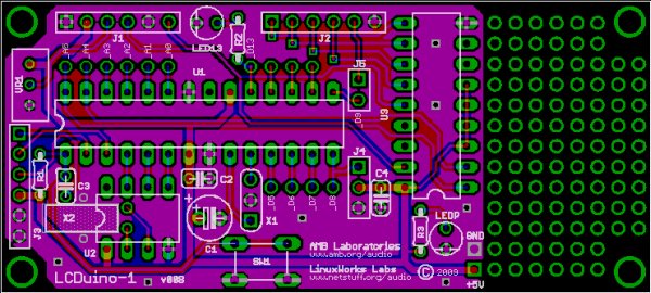
LCDuino-1 is basically an LCD driver circuit based on a customized Arduino platform with some extra features. This board has two 6P pin headers which will mate up with matching receptacles on an industry-standard 2 row x 16 characters LCD module (80mm x 36mm, parallel interface, 5V DC, low-power backlighting). These LCD modules are available in various colors and backlighting, transmissive or transflective. Here are some examples of usable LCD modules. The LCDuino-1 has the same form-factor as the LCD module, with matching screw hole locations. When mated together, they become a two-board “sandwich” that is easily mounted to an enclosure’s front panel. LCDuino-1’s slim profile allows the assembly to fit in a 1U rack case. Off-the-shelf front bezels are available for these LCD modules.
Depending on the nature of the application, the LCD display would show the current input/output selection, a volume control bargraph, the date and time (see below), or some other information as appropriate.
It is worth noting that the LCD module is actually optional, LCDuino-1 could function without one. There may be applications where no display is required, yet LCDuino-1 could still serve as the control center.
The main component on LCDuino-1 is the Atmel ATMEGA328P microcontroller. See the datasheet for chip features, you’ll notice that amongst other features, this microcontroller offers many digital and analog I/O ports, I²C serial bus support and serial UART for program download, making it very versatile as a monitor and controller for devices. The microcontroller is clocked by a 16MHz ceramic resonator, and has an onboard pushbutton reset switch should the need arise.
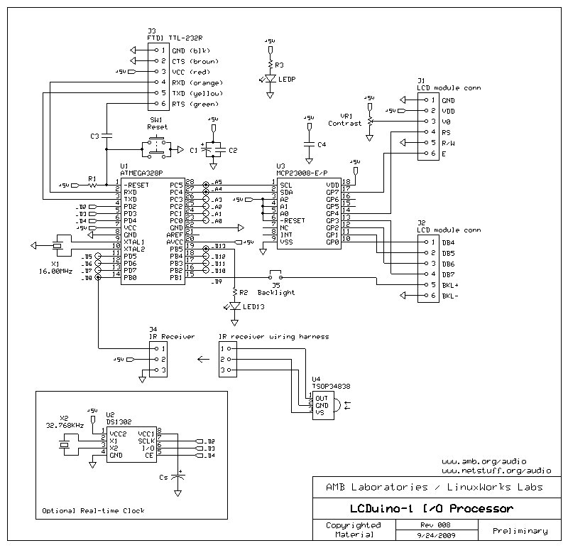 On the LCDuino-1, the I²C bus is connected to an onboard MCP23008 port expander chip, which gives us 8 more I/O ports. Six of these ports are used for controlling the LCD module. This means that we only consume 2 of the microcontroller’s ports to operate the LCD module (plus one more port for the backlight). The I²C bus can be extended offboard to other devices (see “Application modules” below).
An optional real-time clock chip DS1302 may be populated (clocked with a 32.768KHz crystal and could be backed up with an optional 0.022 Farad supercapacitor). This allows the LCD display to double as a date/time clock. The real-time clock option consumes three of the microcontroller’s ports.
A 3P pin header is provided to connect a Vishay TSOP34838 infrared receiver for remote control purposes. The infrared receiver’s output uses up one microcontroller port. The module should be mounted on the enclosure’s front panel.
For more detail: The LCDuino-1 I/O processor
- What is the main function of LCDuino-1?
LCDuino-1 serves as an Arduino-based LCD driver and I/O processor that acts as the control center for an extensible modular system. - Which microcontroller is used on LCDuino-1?
The board uses an Atmel ATMEGA328P microcontroller. - How does LCDuino-1 drive the LCD using few MCU ports?
It uses an MCP23008 I²C port expander so six LCD control ports come from the expander, consuming only two microcontroller ports plus one for the backlight. - Is the LCD module required for LCDuino-1 to function?
No, the LCD module is optional; LCDuino-1 can function without the display. - Can LCDuino-1 provide date and time on the display?
Yes, by populating the optional DS1302 real-time clock chip with a 32.768KHz crystal and optional supercapacitor backup. - Does LCDuino-1 support remote control input?
Yes, a 3P header is provided to connect a Vishay TSOP34838 infrared receiver for remote control, using one microcontroller port. - Can the I²C bus be extended to other devices?
Yes, the I²C bus is available on board and can be extended offboard to other devices and modules. - What display form-factor does LCDuino-1 match?
LCDuino-1 matches industry-standard 2x16 character LCD modules (80mm x 36mm) with matching screw hole locations for sandwich mounting.