Summary of DIY SWR and Power Meter
The article describes a homebrew SWR and power meter based on a modified circuit from "Arduino Projects of Amateur Radio." It uses two AD8307 log amplifiers connected to a directional coupler, with signals amplified by an LM324 op-amp to provide a reference voltage for the Arduino Nano’s AREF. The device monitors input voltage and outputs readings on a larger LCD screen. The PCB was designed in Eagle and fabricated by Elecrow. Issues included an Arduino power connection error due to footprint mistakes and op-amp oscillations, resolved by removing certain capacitors. The design is simple, precise, and button-free, focusing on basic SWR measurement.
Parts used in the Homebrew SWR and power meter:
- AD8307 log amplifiers (two units)
- LM324 operational amplifier (quad op-amp)
- Arduino Nano microcontroller
- Directional coupler
- 20x4 LCD display
- Power jacks (two units)
- Printed Circuit Board (custom designed)
Homebrew SWR and power meter
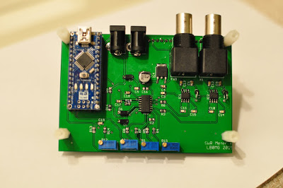
I opted for using an Arduino nano instead of installing an AVR328 on the circuit and dealing with USB converters. I am happy that I did it. I made a single error on the board though. The Arduino did not receive power from the 5V line. The issue occurred due to a mistake in the Eagle footprint for the Arduino Nano. I recently downloaded the footprint file without verifying its validity. Besides that, it was okay.
Another issue was the occurrence of oscillations in the LM324 opamps that were linked to the AD8307. The frequency of the oscillations was approximately 40KHz, with an amplitude of around 400mVpp superimposed on the DC signal. Therefore, calibrating the device was not possible. Desoldering the output capacitors on the LM324 was the solution. I believe they are not necessary for a DC design.