Summary of DIY Motion Sensor Alarm System
This article details a DIY motion alarm system built with an Arduino Uno to alert users of nearby movement, ideal for those with hearing difficulties or in noisy environments. The project is compact, fitting into a card box, and costs approximately $13. It combines a PIR sensor, LED, and speaker controlled by custom code to detect motion and trigger visual and audio alerts.
Parts used in the Motion Alarm System:
- Arduino Uno
- Parallax PIR Sensor
- PC Board
- Assorted Wire
- Small Speaker
- Solder
- Card Box
- Spray paint
- Zip Ties
- LED
Are you constantly being scared when people sneak up behind your back? Do you have bad hearing and can’t hear people approaching you? Do you want to just build a super fun Arduino project?
 If you answered yes to any of those questions, then this project is for you! I have a workbench in my basement that I use all of the time for homework and projects. The bench is right next to my furnace which is very loud when running. Whenever someone comes in my basement, it scares the life out of me. I made this to alert me when someone is coming. This is a motion alarm system that alerts you whenever motion is detected around you. It uses an Arduino Uno to control the PIR motion Sensor, LED, and the speaker. It is all enclosed and fits in a box from a deck of cards! It is powered using the USB power cord for the Arduino. To program the Arduino, you can make your own sketch, or use mine in the upcoming step. The whole project will probably only take you a day or two and anyone should be able to do it. I am 14 years old, and lacking the ability to buy a lot of parts, so I try to do the best with what I have.
Step 1: Tools and Materials
Not many materials or tools are required for this project. I only spent about $13.00 on this project.
Materials:
An Arduino Uno
Parallax PIR Sensor (RadioShack- $9.99)
A PC Board (RadioShack- $2.49)
Assorted Wire. (Depending on how far away you want the sensor to be)
Small Speaker (anything should work)
Solder
Card Box (optional)
Some spray paint
Zip Ties (optional)
An LED of your choosing
Wire Strippers
A Small Saw
A Drill or Drill Press
A computer and Arduino USB cable
Soldering iron
Step 2: The PIR Sensor

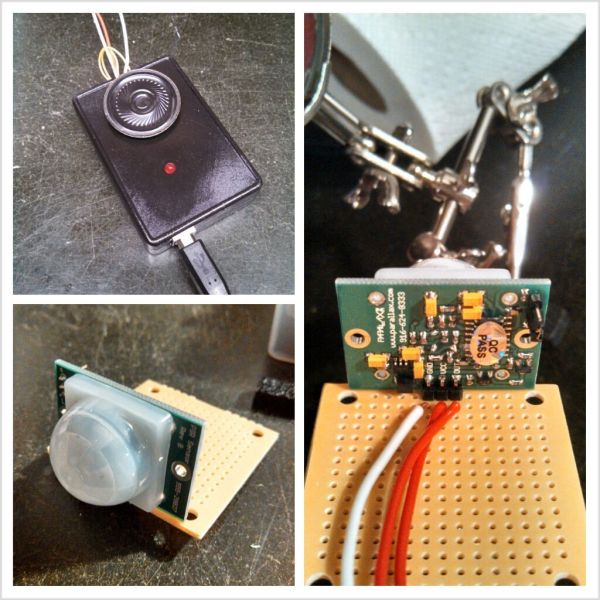
First, we are going to put together the motion Sensor! So go ahead and open up the sensor and the printed circuit board. I cut mine in half since I didn’t need the whole thing and could use the other half for other projects.
Once you have both out of the packages, position the three pins from the sensor onto the PCB. Look at the picture to help you. Once you have it positioned on the front row, go ahead and solder it to the board. Make sure you solder on the side with the metal pads, not the blank side.
Once you have it soldered on completely, look closely at the pins. Above them it should say “VCC” “GND” and “OUT”. The VCC is where you plug in the +5V the GND goes to ground and the OUT will go to digital pin 7 on the Arduino.
Next, solder three wires right behind where you soldered the three pins just like in the picture. On the bottom of the board you should have 6 solder points. This needs to turn into 3. Connect each pin to a wire you just soldered. The picture explains better than I do. Make sure the wires you solder on are long enough to position the sensor where you want, whether that is right next to you or all the way across the room.
Step 3: Arduino
Next, we need to set up the Arduino. First, the wire connections. Connect the wire that goes to the sensor’s GND to the ground on the Arduino. Now connect the VCC to the +5V on the Arduino. Last, connect the OUT to pin #7.
At this time you can also grab the LED and speaker you’ve retrieved. Connect the + of the speaker to pin #9 and the – to ground. Next, connect the long leg of the LED to pin #13 and the shorter one to the ground right next to pin #13.
Now for the Arduino sketch. You can copy and paste the following into your Arduino IDE:
For more detail: DIY Motion Sensor Alarm System
- What is the main purpose of this project?
The project is a motion alarm system designed to alert you whenever motion is detected around you. - How much did the author spend on materials?
The author spent about $13.00 on the project materials. - Can I use a different box for the enclosure?
The article mentions using a card box but lists it as optional. - Which digital pin connects to the PIR sensor output?
The OUT pin from the sensor connects to digital pin 7 on the Arduino. - How do you connect the speaker to the Arduino?
The positive leg of the speaker connects to pin 9 and the negative leg connects to ground. - What tool is needed to cut the PC board?
A small saw is listed as one of the required tools for cutting the board. - Is programming the Arduino difficult?
The author states anyone can do it and provides a sketch to copy and paste. - Does the project require external power sources other than USB?
No, the project is powered using the USB power cord for the Arduino.