In this tutorial we’re going to make an internet connected smart lamp. This will go deep into internet of things and opens up a world of home automation!
The lamp is WiFi connected and built to have an open message protocol. This means you can select whatever control mode you want! It can be controlled through a web browser, home automation apps, smart assistants like Alexa or Google Assistant, and so much more!
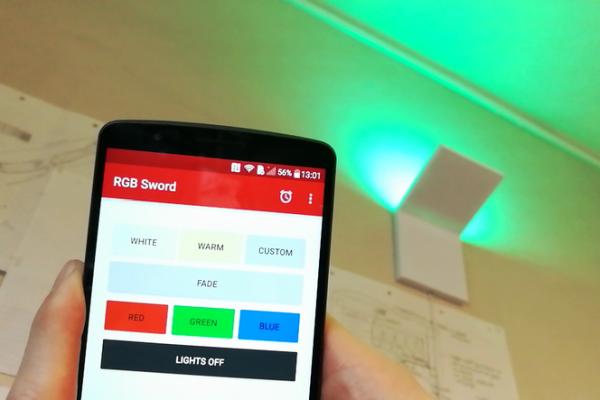
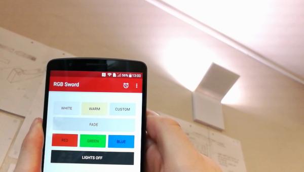
As a bonus this lamp goes along with an app to control the project. Here you can select different color modes, fade between RGB colors, and set timers.
The lamp consits of an LED board and a control board. The LED board uses three different types of LEDs for a total of five LED channels! This is RGB along with both warm and cold white. Because all of these channels can be set individually, you have a total of 112.3 peta combinations!
Let’s get started!
Step 1: Parts and Tools
Parts
- Wemos D1 Mini
- 15 x Warm white 5050 LEDs
- 15 x Cold white 5050 LEDs
- 18 x RGB 5050 LEDs
- 6 x 300 ohm 1206 resistors
- 42 x 150 ohm 1206 resistors
- 5 x 1k ohm resistors
- 5 x NTR4501NT1G
- MOSFETs
- Linear voltage regulator, 5V
- PCB
- Download the gerber files in the circuit step to make your own PCBs
- PSU 12V 2A
Tools
- Soldering iron
- Soldering tin
- Liquid soldering flux
- Masking tape
- Double sided tape
- 3D printer
- Wire strippers
Step 2: The Plan
The complete project consists of four main parts:
- Circuit
- The circuit is made on a PCB. The completed circuit will consists of more than 100 individual components. It’s a huge relief not to wire all those by hand on a perfboard!
- Arduino Code
- I’m using the Wemos D1 Mini which uses an ESP8266 as a WiFi connected microcontroller. The code will start a server on the D1. When you visit the address of this server the D1 will interpret this as different commands. The microcontroller then acts on this command to set the lights accordingly
- Remote Control
- I made an app just for this project to make it as easy as possible to control the lamp to your liking
- The smart lamp can really be controlled by anything capable of sending an http GET request. This means the lamp accepts commands from nearly a limitless array of devices
- 3D Printing
- This smart lamp deserves a cool looking case. And like so many projects were you need a cool case, 3D printing comes to the rescue!
Step 3: Circuit
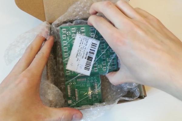
I ordered my PCBs from jlcpcb.com. Full disclosure time: they also sponsored this project.
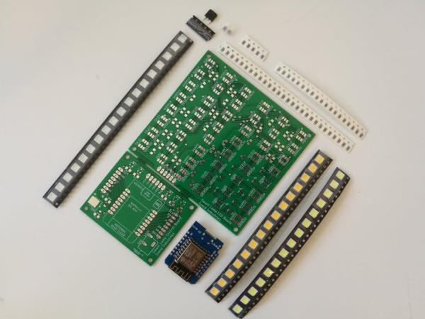
The PCB consists of two parts. It has the LED board and the control board. The PCB can be snapped apart to later connect these two parts by flexible wire. This is necessary to both keep the 3D printed lamp slim, and to angle the LED board to spread the light evenly through the hole room.
The control board houses the D1 microcontroller along with five MOSFETs for dimming the LEDs, and a voltage regulator to give the microcontroller a smooth 5V.
The LED board has five LED channels in three differetn types of LEDs. Because we use a 12V power source the LEDs are configured as three LEDs in series with a resistor and then repeated 16 times in parallel.
A regular white LED usually draws 3.3 V. On a segment of the board, three of these LEDs are in series which means the voltage drop is aggregated in the circuit. Three LEDs that draws 3.3 V each means one segment of LEDs draws 9.9 V. The circuit is powered by 12 V so that leaves 2.1 V.
If the segment only consisted of the three LEDs they would get more voltage than they dissipate. This is not good for the LEDs and can quickly damage them. This is why each segment also has a resistor in series with all three LEDs. This resistor is there to drop the remaining 2.1 V in the series junction.
So if each segment accounts for 12 V that means each of the segments are connected to each other in parallel. When circuits are connected in parallel they all get the same voltage and the current is aggregated. The current in a series connection is always the same.
A regular LED draws 20 mA in current. This means a segment, which is three LEDs and a resistor in series still will draw 20 mA. When we connect several segments in parallel, we add the current. If you cut six LEDs from the strip, you have two of these segments in parallel. Which means your total circuit still draws 12 V, but they draw 40 mA in current.
Step 4: Soldering LEDs
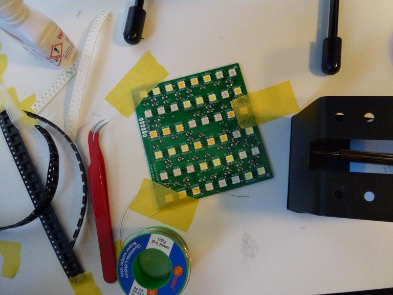
From trying a few things I’ve found simple masking tape is just the most effective and flexible for keeping the PCB from moving around.
For parts with multiple pins, like the 6-pins on a 5050 LED, i start by placing down solder on one of the PCB pads. Then it’s just a matter of keeping this solder molten with the soldering iron while sliding the component into its place with a pair of tweezers.
Now the other pads can be easily tacked on with some solder. However, to speed up this work I suggest picking up some liquid solder flux. I really cant recommend this stuff enough.
Apply some of the flux to the solder pads, then melt some solder on the tip of your soldering iron. Now it’s just a matter of bringing the molten solder onto the pads and everything flows into place. Nice and simple.
When it comes to the resistors and other two-pad components no solder flux is really needed. Apply solder to one of the pads and bring the resistor into place. Now just melt some solder onto pad number two. Easy peasy.
Take a look at the fifth picture in this step. Pay attention to the orientation of the LEDs. The warm and cold white LEDs have their notch oriented in the upper right corner. The RGB LEDs has their notch in the bottom left corner. This is a design error from my part, because I couldn’t find the datasheet for the RGB LEDs used in this project. Oh well, live and learn and all that!
Step 5: Soldering Control Board
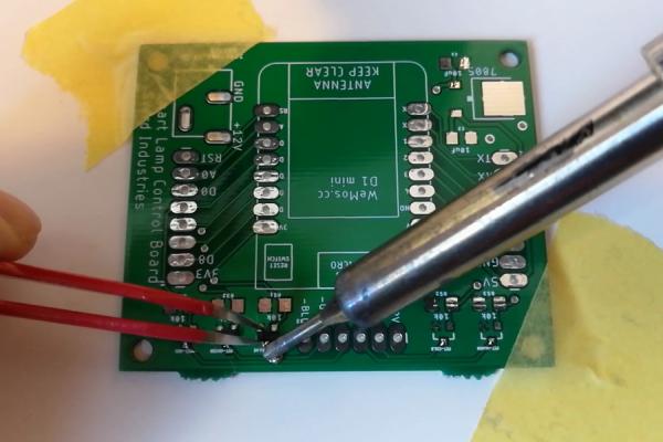
After finishing the marathon of the LED board, the control board is a breeze to solder. I placed down the five MOSFETs and matching gate-source resistors, before moving onto the voltage regulator.
The voltage regulator has optional spaces for smoothing capacitors. While I soldered them in this picture I ended up removing them because they were not really necessary.
The trick to getting a slim control board is to put the pin headers poking out the top through the bottom. After the pins are in place, the unused length can be snipped from the backside along with the black plastic. This makes the bottom side completely smooth.
With all the components in place it’s time to bring the two boards together. I just snipped and stripped six small 2.5 inch (7 cm) wires and connected the two PCBs.
Step 6: WiFi Setup
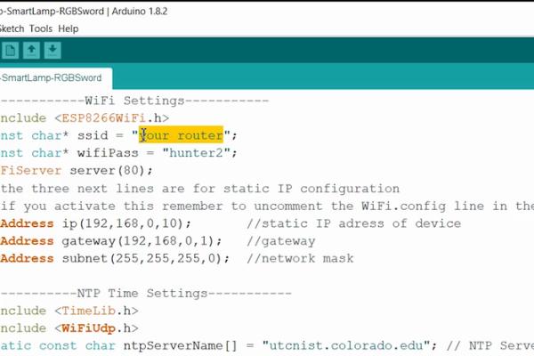
There are six simple lines in the code you need to change.
- ssid, line 3
- Your router name. Make sure you get the letter case correct when writing this
- wifiPass, line 4
- Your router password. Again, pay attention to casing!
- ip, line 8
- The static ip address of your smart lamp. I chose a random ip address on my network and tried to ping it in the command window. If there’s no reply from the address you can assume its available
- gateway, line 9
- This will be the gateway on your router. Open a command window and type “ipconfig”. The gateway and subnet are circled in red in the picture
- subnet, line 10
- As with the gateway, this information is circled in the picture for this step
- timeZone, line 15
- The timezone you’re in. Change this if you want to use the built in timer functions to turn on and off lights at specific times. The variable is a simple pluss or minus GMT
Source: DIY IoT Lamp for Home Automation || ESP8266 Tutorial