Summary of DIY handmade Hexapod with arduino (Hexdrake)
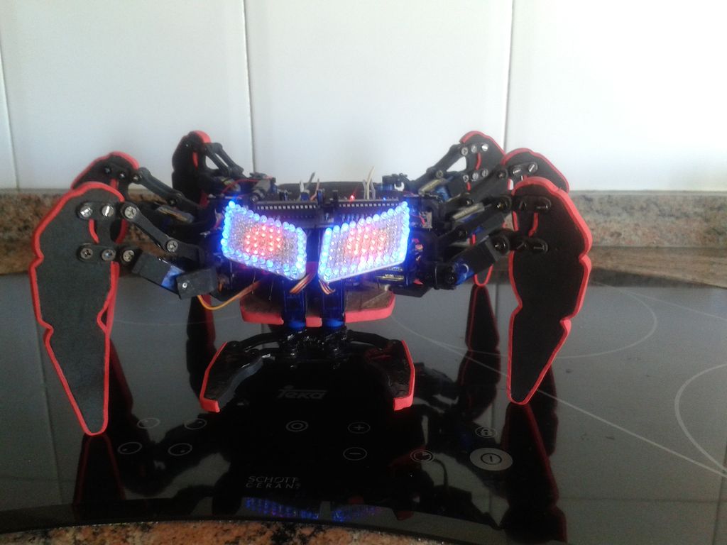
David built "Hexdrake," a low-cost, 2-DOF hexapod robot using hand-cut wood and SG90 servos. The project features a custom body with an LED eye matrix and a remote controller equipped with joysticks and an accelerometer for wireless operation.
Parts used in the Hexdrake:
- 2 x 3mm wooden planks
- Sheet of aluminium and heatsink from old car radio
- Black acrylic paint
- EVA foam (red and black)
- 50-55 screws with nuts
- 14 SG90 micro servos
- USC 16-channel servo controller
- Arduino UNO board
- UBEC 8A/15A Voltage Regulator
- LiPo battery
- Copper PCBs
- Blue and red LEDs
- Red and black wires
- 2 Atmega8 ICs
- 28 pin socket
- 16 MHz crystal oscillator
- 4 22pF ceramic capacitors
- Lm7805 regulator
- 12 220 Ohm resistors
- Cables
- 2 PS2 Joysticks
- Screw terminal blocks
- 10K ohm resistors
- Breadboard (700 points)
- 50Kohm slide pot
- Arduino nano V3.0
- MMA7361 3 axis accelerometer
- NRF24L01 2,4 GHz Transceiver module
Hello, I’m David and in this instructable I’ll show how I made this hexapod whose name is Hexdrake.
Since I was 16 I became interested in electronic and later in robotics. After getting some level and programming skills using arduino I decided to build a robot something more interesting than a simple robot with two wheels . I liked the idea of having a hexapod but did not have much money to buy one.
So I built a low cost 2DOF hexapod made with hand-cut wood and Sg90 servos.
Step 1: Parts needed
- For the hexapod:
- Body and jaw:
- 2 x 3mm wooden planks.
- Sheet of aluminium, and a heatsink from an old car radio.
- Black acrylic paint.
- EVA foam (red and black).
- A lot of 3 mm screws with nuts (About 50-55).
- 14 servos (12 for body and 2 for the jaw): http://www.ebay.es/itm/10pcs-SG90-Micro-Servo-9g-F…
- USC 16-channel servo controller: http://www.ebay.es/itm/16-Channels-Servo-Steering-…
- An Arduino board. For example UNO: http://www.ebay.es/itm/UNO-R3-Mega-2560-Pro-Mini-N…
- UBEC 8A/15A Voltage Regulator: http://www.ebay.es/itm/Hobbywing-UBEC-8A-Max-15A-S…
- LiPo battery: http://www.ebay.es/itm/1300mAh-7-4V-25C-2s-LiPo-Ba…
- Eyes and controller:
- Copper PCB: http://www.ebay.es/itm/10-15cm-10cmx15cm-Single-PC…
- Blue and red leds. (Each eye needs 32 blue leds and 45 red for the matrix) http://www.ebay.es/itm/100pcs-F3-3mm-Blue-Round-Su… http://www.ebay.es/itm/100pcs-3mm-RED-Round-Superb…
- Red and black wires.
- 2 Atmega8: http://www.ebay.es/itm/5PCS-NEW-IC-ATMEL-DIP-28-AT…
- 28 pin socket: http://www.ebay.es/itm/10-x-28-pin-DIP-IC-Socket-S…
- 16 MHz crystal oscillator: http://www.ebay.es/itm/10Pcs-New-16-000MHZ-16MHZ-1…
- 4 22pF ceramic capacitor: http://www.ebay.es/itm/50-x-22pF-50V-Ceramic-Disc-…
- Lm7805 regulator: http://www.ebay.es/itm/5-x-LM7805-L7805-7805-Volta…
- 12 220 Ohm resistors: http://www.ebay.es/itm/NEW-100-X-Resistor-220-Ohms…
- A lot of cables: http://www.ebay.es/itm/65Pcs-Male-to-Male-Solderle…
- Body and jaw:
- Remote Controller:
- Copper PCB: http://www.ebay.es/itm/10-15cm-10cmx15cm-Single-PC…
- 2 PS2 Joysticks: http://www.ebay.es/itm/Brand-New-Analog-Joystick-C…
- Screw terminal blocks: http://www.ebay.es/itm/3-x-DG301-Screw-Terminal-Bl…
- 10K ohm resistors: http://www.ebay.es/itm/100pcs-1-4w-Watt-10K-ohm-10…
- Bread board(Y use one with 700 points): http://www.ebay.es/itm/Mini-PCB-Breadboard-700-Poi…
- 50Kohm slide pot: http://www.ebay.com/itm/2pcs-50K-ohm-Potentiometer…
- Arduino nano V3.0: http://www.ebay.es/itm/UNO-R3-Mega-2560-Pro-Mini-N…
- MMA7361 3 axis accelerometer: http://www.ebay.es/itm/New-MMA7361-Angle-Sensor-Ac…
- NRF24L01 2,4 GHz Transceiver module: http://www.ebay.es/itm/2x-NRF24L01-2-4GHz-Antenna-…
- Software:
- Arduino IDE
- AutoCad 2012
- USC Software
- Tools
- Saw
- Lime
- Electric Drill
- Glue(cyanoacrylate glue)
- Tweezers
- Toilet paper
- Scissors
- Rule
- Pencil
- Screwdriver
Step 2: Designing the parts and making the templates
I designed the pieces according to the size of SG90 servos. The CAD file is only for reference. I designed the templates before on paper. I used a sheet of wood about 3 mm of thick. After having the templates the next step is to pass them on to the wooden board.
According to the size of the servo the number of pieces are:
48x A part
6x B
12x C
12x D
12x E
12x F
12x G
12x H
6x I
2x J
Step 3: Time to cut!!!
Tools for this Step:
Saw, lime, electric dril and a good hand.
Before cutting some pieces is easier to drill the holes using a 3mm drill. I advise to use a fine saw to cut all the pieces accurately. After cutting each piece file the edges to be soft.
Step 4: Glue certain parts between them
Tools for this step:
Glue(cyanoacrylate glue for more strength), tweezers, toilet paper (to clean the excess glue).
To make the main parts of each leg, where the servos are subject I needed to glue 4 A pieces. Then, for each leg glue a piece B with C. And the last thing to be done is to glue two H pieces together.
*Be careful to align the holes well of certain pieces or can also be done is glue before and then do drills the holes.
Step 5: Painting and Decorating
Materials and tools for this step:
EVA foam(red and black), glue, scissors, rule, pencil and black acrylic paint.
For a more professional finish I paint some of the pieces with black acrylic paint, and cover the body and legs with black and red EVA foam.
Step 6: Attaching the servos to the legs and body
Materials for this step:
A lot of screws, screwdriver and 12 SG-90 servos.
Step 7: Add electronics and connect.
Electronic:
An arduino. USC 16-channel servo controller, UBEC 8A hobbywing, lipo battery.
Power supply:
The servo controller needs two power supplies: servo power supply and chip power supply.
–Servo power supply (+): VS (left of the blue connecting terminal at Position 3 in the figure)
–Servo power supply (‐): GND (middle of the blue connecting terminal at Position 3 in the figure)
Servo power supply’s parameters depend on the parameters of the attached servo. For example, if the SG-90 servo has a power supply of 4V‐5V, the servo power supply can use the power source of 4‐5V.
–Chip power supply (+): VSS (right of the blue connecting terminal at Position 3 in the figure)
–Chip power supply (‐): GND (middle of the blue connecting terminal at Position 3 in the figure)
There is a VSS requirement of 6.5‐12V. If the chip power is input through the VSS port, the power supply has to range from 6.5 to 12V.
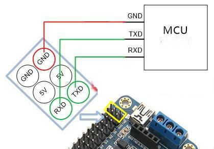
Connecting Arduino, USC and servos:
What is marked red in the figure are the servo’s connectors for signal wires (be careful about the direction when
connecting to the servo).
To connect the USC controller simply connect the rx of the USC to the tx of arduino and the tx pin with the rx pin of the USC. And connect GND pin of USC with arduino.
 rios_usc.exe3 MBusc_driver.exe1 MB
 usc_en.pdf431 KB
- How many servos are required for the entire project?
The project requires 14 servos in total, with 12 used for the body and 2 for the jaw. - What materials were used to construct the body and legs?
The body and legs are made from 3mm wooden planks, EVA foam, and black acrylic paint. - Can I use different power voltages for the servos and the chip?
Yes, the servo power supply should be 4V to 5V, while the chip power supply via the VSS port must range from 6.5V to 12V. - Which software tools are necessary for this build?
The required software includes Arduino IDE, AutoCad 2012, and USC Software. - What is the specific connection method between the Arduino and the USC controller?
You must connect the RX of the USC to the TX of the Arduino, the TX pin to the RX pin of the USC, and the GND pins together. - How many pieces of each type are needed for the wooden templates?
The design requires 48 A parts, 6 B parts, 12 C, D, E, F, G, and H parts, 6 I parts, and 2 J parts. - What tools are recommended for cutting the wooden pieces accurately?
A fine saw, lime, electric drill, and a good hand are advised for accurate cutting and drilling. - Does the remote controller include an accelerometer?
Yes, the remote controller uses an MMA7361 3-axis accelerometer.