
Summary of DIY FPGA-based HDMI ambient lighting
This project details the construction of a basic FPGA-based ambient lighting system using HDMI signal processing. Unlike commercial solutions, this DIY approach decodes and recodes video signals to extract pixel data for driving LEDs, ensuring compatibility with various sources like consoles and DVD players without altering the original output. Although current hobbyist FPGA limitations restrict resolution to 720p, the system effectively creates a ring of light around a display by aggregating pixel values.
Parts used in the FPGA-based HDMI Ambient Lighting System:
- FPGA board (Scarab miniSpartan6+)
- HDMI connectors
- LED strand
- SPI interface
- DVD player or video game console (input source)
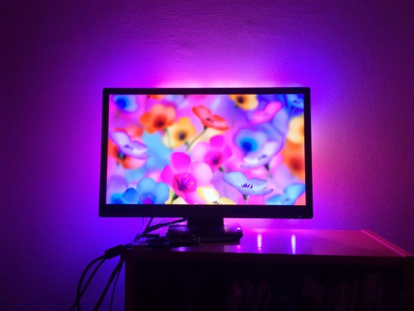
Ambient lighting is a technique that creates light effects around the television that correspond to the video content. It has been pioneered by Philips under the brand Ambilight. In this project we will create a basic FPGA-based ambient lighting system that reads the video signal over HDMI. This means we are not limited to computer output. We can use it together with DVD players, video game consoles, etc.
Design outline
Ideally we would like to snag the signal off the HDMI cable without disturbing it. However, the signals are really really fast current mode logic differential pairs, and signal integrity issues make any kind of passive tap a non-starter. We are stuck with doing the next best thing: decoding and recoding the signal. This has the advantage that we gain the ability to modify the signal on the way through the system to add debug information etc.
Thanks to our “man in the middle” position between the player and the display we can see all the pixel values, aggregate them in properly sized and positioned boxes and use this signal to drive a strand of LEDs over their SPI interface. These LEDs will be arranged in a ring around the back of the display, resulting in an ambient lighting effect.
Meet the components
At the heart of the system is the FPGA. We are going to save ourselves a lot of trouble, and use a board that comes with an FPGA suitable for HDMI deserialisation/serialisation and two HDMI connectors already affixed. We are going to use the wonderful Scarab miniSpartan6+.
For More Details: DIY FPGA-based HDMI ambient lighting
- How does the system capture video content?
The system decodes and recodes the HDMI signal to access pixel values. - Can I use this with devices other than computers?
Yes, it works with DVD players, video game consoles, and other HDMI sources. - Why not tap the HDMI cable directly?
Signal integrity issues with fast current mode logic differential pairs make passive taps unfeasible. - What is the maximum resolution supported?
Current hobby budget FPGA boards limit the system to 720p resolution. - How are the LEDs controlled?
A SPI interface drives the LED strand based on aggregated pixel data. - Where are the LEDs positioned?
The LEDs are arranged in a ring around the back of the display. - What specific FPGA board is recommended?
The Scarab miniSpartan6+ is used because it includes necessary HDMI connectors.
