Hello there! I hope you all are fine and in good health. This instructable is about making your own current sensor that is compatible with Arduino and most other widely popular microcontrollers. This project features a compact design and an all SMD component based circuit, making this sensor module very compact for it’s range.
This current sensor can easily be used for measuring currents up to 15 Amps constant and can even handle about 20 Amps peak. I had previously built a shunt current measurement module using a home made shunt but it had a few limitations- The wire was quite long which may not be suitable for small devices. It also got rusted over time and one major drawback was heating at higher currents even at 10 amperes. Well, this module solves almost all of these problems in a more efficient design.
This was a great learning project for me and I hope it will be same for you as well!
Let’s get started 🙂
As with previous tutorials, the detailed videos is attached here:
Step 1: Gather Your Components
This build is a pretty simple build and does not require a whole lot of components. How ever a few essential things are required to make the PCB since it is a SMD based circuit.
Here are all the components you will need:
- LM358 general purpose dual OP-Amp IC (SMD version)
- 2.2 KiloOhm resistor (222- SMD code)
- 100 KiloOhm resistor (104-SMD code)
- 1uF SMD capacitor – 2
- 100nF or 0.1uF SMD capacitor – 1
- 5 MilliOhms shunt resistor (R005 SMD code)
- Screw terminal – 1
- 3 pin male header – 1
- Multimeter
- Small piece of copper clad board
- Ferric Chloride solution for etching
- Hand drill or a mini drill with bits of 1.2mm and 0.8 mm diameter
- A print out of your circuit on a glossy paper for toner transfer(I’ll discuss this in detail in upcoming step)
- Pliers, tweezers and other accessories
- Small plastic container for performing the etching process
- Fine tip soldering iron
- Good quality solder and flux
- A bit of patience to solder SMD components!
Step 2: The Shunt Resistor
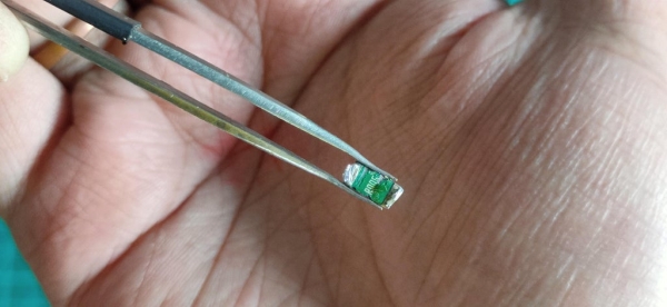
The main component and probably the most crucial one in this build is the shunt resistor. It is by this resistor that we measure a small voltage drop and then amplify to measurable limits for the arduino or any other microcontroller. It is important that the value of this resistor is small enough as to not create a significant voltage drop in the load circuit in which we are trying to measure current. Small resistance in the range of milliohm also ensures that the total power dissipated is very small and thus the resistor itself does not heat up. The voltage drop is quite small for a microcontroller to directly measure it, so we are using the OPAmp as an amplifier.
The shunt used in my circuit has the label –R005 which means it has a resistance of 5 MilliOhms- perfect for our use!
I got this out of an old laptop battery pack but you can easily get it online or from local electronics store.
Step 3: A Little Bit of Theory
The main concept of shunt based current measurement system to create a very small voltage drop across the shunt resistor and then to amplify if using suitable amplification techniques whose output can then be measured by a microcontroller or some other data acquisition system.
Considering that the resistance of the shunt remains fairly constant, it is safe to say that the voltage drop is directly proportional to the current through the load using the Ohm’s Law concept (V= I * R).
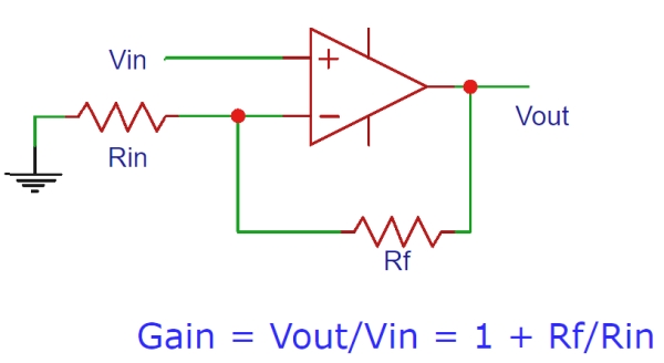
This small voltage drop is then amplified by an Op-Amp configured as a non-inverting amplifier. As you can see from the figure that the gain is determined by two resistors Rf and Rin.
In my application Rf= 100K and Rin= 2.2K so we have a gain of approximately 46, as per the formula.
Note that out shunt resistor lies between the load and the round connection and the positive supply is directly connected to the load. This topology is called low side measurement. This has a good advantage of having the ground common to both the load and the measuring circuit so the small voltage drop across the shunt is directly measured with respect to ground.
Step 4: Designing the Circuit
With the theory in mind, it was now time to design a suitable schematic and then create a PCB layout for the same.
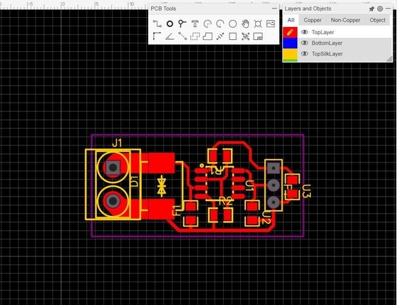
I have used the Easy EDA online software for designing this simple circuit and then exported the PDF of the layout which I will have to print for the toner transfer method.
I have attached the PF for your reference in case you want to use the same.
Step 5: Cutting the Copper Board to Shape
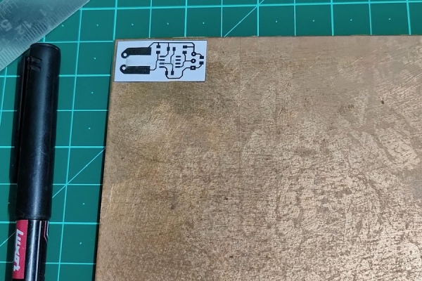
After completing the schematic and layout design, I exported the layout and printed it to scale such that the print size matches the actual PCB size as intended. This print was then my reference to cut out a small piece of copper board according to size. I marked the boundaries using permanent marker and then cut the copper board using a dremel tool. You can also use a hacksaw.
Step 6: Sanding Off the Oxide Layer
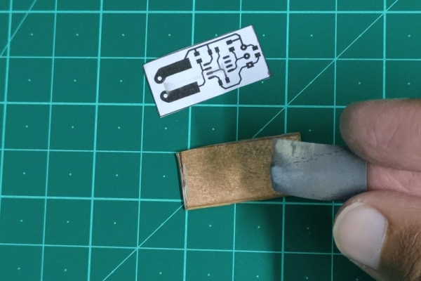
Copper when left exposed to air for a long time tends to form a oxide layer which can effect the overall conductivity. it is important that this oxide layer is removed using a very fie sand paper of a scrubber.
Gently use the sand paper to remove the oxide layer. Make sure to do it gently because applying too much pressure will cause the actual copper layer to deplete which is not what we want.
At the end we will have a shiny copper clad board as shown ready for toner transfer.
Step 7: Toner Transfer
For the toner transfer method, we actually need to mirror the PCB layout and then print the mirrored layout in a glossy paper. In the 1st image you can see the actual PCB layout and the corresponding mirrored version that we will use to flip and eventually transfer the toner ink onto the copper surface so that we again get out original layout on the board.
Keep the glossy paper faced down onto the copper board and using a iron apply constant heat and pressure so that all the toner ink gets transferred to the copper.
After that dip the board in water and after 10 minutes slowly peel off the paper leaving behind only the ink on copper. Do this very gently without using any pointed object.
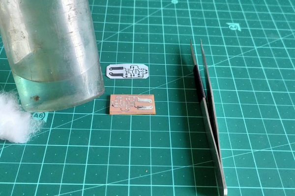
Step 8: Etching the Board
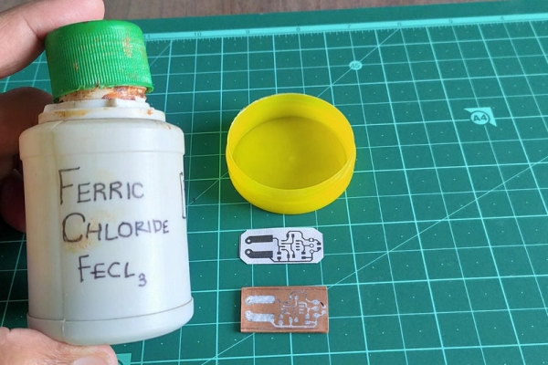
Now with the toner set on the board, it is time to remove the unwanted copper off the board. For this I will be using the popular ferric chloride solution.
I used a small container and poured a little amount of the solution and then immersed the board into the solution and kept it in there for 10 minutes with occasional stirring to speed up the process. You can see that the unwanted copper is etched out in the last image.
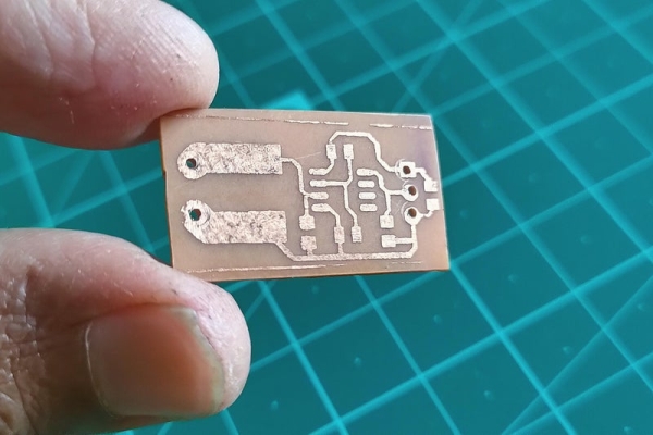
Step 9: Cleaning the Board
After etching process, te ink needs to be removed from the copper layout for which I have used some acetone and using some cotton gently removed the ink, exposing the copper layout.
Step 10: Drilling Holes for THT Components
I have used a hand drill with a bit size of 0.8mm for the male header pins and 1.2 mm for the screw terminal.
Step 11: Soldering the Components
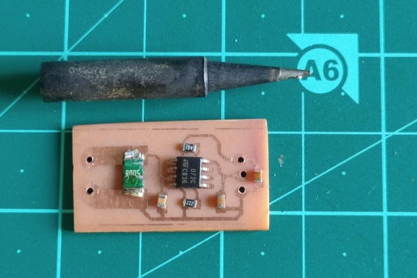
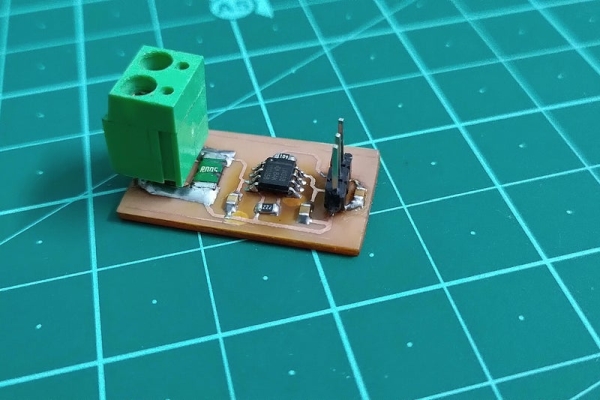
With our PCB now finally complete, let’s move onto the soldering process. As you can see that I have placed all the components in their respective places for soldering.
Unfortunately I do not have a hot air station so I will have to do the soldering using an iron. This process is a bit tricky and required patience. The main thing here is to have a fine tip soldering iron so as to allow good contact with SMD pins but not have to much solder on the tip so as to short two pins together, basically, finer the tip the better results you’ll get.
Step 12: And Done!
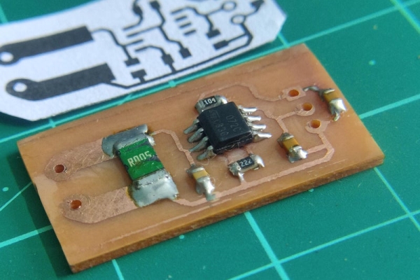
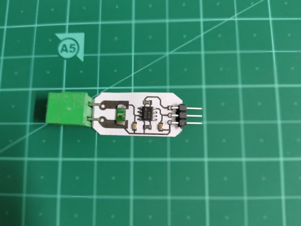
After about 15 minutes, the soldering process was complete for the SMD components. All that is left is to solder the Screw terminal and the header for which there are two possible orientations. one is to solder on the copper side where as the other option is to ass those components to the other side. This is more clear through images attached in this step. I went ahead and soldered them on the copper side itself. this requires some skill but keeps the overall form factor nice.
Step 13: Coding and Calibration
With our hardware potion complete it is now time for coding the microcontroller and calibrating the sensor values to give accurate readings.
To keep things simple I have used the Arduino Nano which I have programmed in the Arduino IDE itself to keep things simple. You can easily port this code to your favourite microcontroller environment.
Okay the main code can be broken down into the following steps:
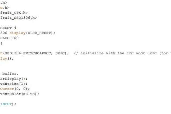
- Initialize the libraries for the OLED display(I have used the Adafruit library for this)
- Configure analog pin 0 as input
- Read the analog value from the output of the OP-Amp at analog pin 0
- Multiply the analog value with the calibration factor to get the correct current reading in Amps(or milliamps)
- Display the value in the OLED display
Now as we know that the OP-Amp acts as a non inverting amplifier in our circuit and produces a voltage that is proportional to the voltage drop across the shunt. This voltage is then measured using the Arduino’s ADC which gives out a number between 0 and 1023 (10 bit resolution of the ADC in arduino). Well this number is certainly not equal to the actual current value so some mathematical manipulation must be done in software to get the accurate value. This is where a Multimeter comes to play. Most multimeters can accurately measure current upto 10 Amps so this can be used as a reference to determine our calibration factor.
The trick is to use a small load along with a power supply with a miltimeter and our current shunt in series with the load.
So here the multimeter can measure the actual current consumed by the load and from our current shunt module, we can get the corresponding analog value via arduino.
The calibration factor can this be calculated as:
Calibration factor = (reading in multimeter / analogRead value of Arduino )
We can re write this as:
current reading = analogRead value * calibration factor and this is exactly what I have done in my code!
Check this line:
float val=analogRead(A0);
float amp=val*0.015426; // this is the calibration factor
I hope this makes sense.
Source: DIY Current Sensor – 2.0