The objective of this project is to create a version of Arduino Mega 2560 board that has lower component count and smaller board size.
Personally to be used for robotics projects that require ATmega2560’s 256 KB flash and digital/analog pins, where the size, weight, and USB port location of the original design is not ideal.
References:
- Mr. Nick Gammon’s How to make an Arduino-compatible minimal board
- TSJWang’s DIY Arduino Mega 2560 or 1280
Electronics/PCB knowledge provided by:
Step 1: Prototype
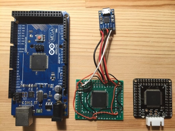
A prototype board was made as proof of concept, the components, placements, and connections are:
- ATmega2560 chip from an Arduino Mega2560 clone (functional chip and bootloader) removed with a hot-air gun, soldered on to a TQFP100 breakout PCB.
- Connect all VCC/AVCC (chip pins 10, 31, 61, 80, 100) together and GND (chip pins 11, 32, 62, 81, 99) together.
- 0.1uF bypass capacitor x 3, connected in parallel to 3 of the VCC/AVCC and GND pairs (chip pins {31,32}, {61,62}, {99,100}).
- 10k pull-up resistor x 1 connected between RESET (chip pin 30) and VCC/AVCC.
- LED x 1 and 1k current limiting resistor x 1 connected between D/13 (chip pin 26) and GND, this is same as the Arduino Mega “L” LED, to be us as indicator to test prototype.
- 16MHz ceramic resonator connected between chip pins 33 and 34, with resonator’s ground pin connected to chip’s GND.
- CP2102 USB to UART TTL Module (one that has a DTR pin), with the connections:
- 0.1uF capacitor x 1 between module’s DTR pin and RESET (chip pin 30).
- Module’s RX to D1/TX (chip pin 3).
- Module’s TX to D0/RX (chip pin 2).
- Module’s 5V to chip’s VCC/AVCC.
- Module’s GND to chip’s GND.
After the driver for CP2102 was installed, a few sample Arduino sketches such as “Blink” and “Fade” were uploaded to make sure the chip was still functioning before designing the board in Eagle PCB.
Step 2: EAGLE PCB: Revision I
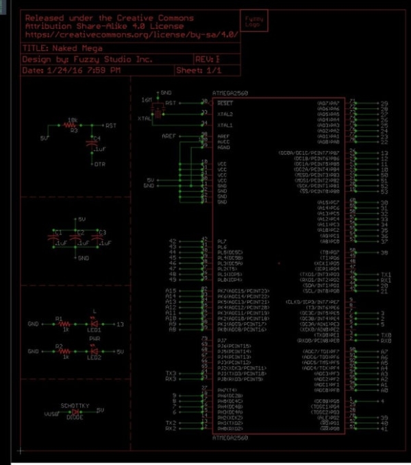
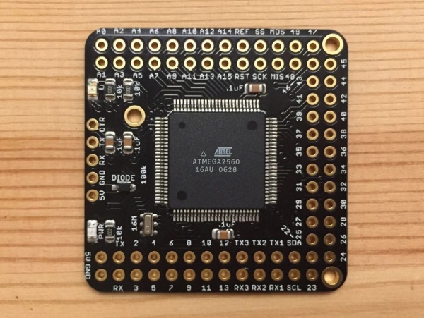
Additional components compared to the prototype board:
- LED x 1 and 1k current limiting resistor x 1 between chip’s AVCC/VCC and GND as power indicator.
- Schottky diode between CP2102 module 5V input pin and onboard 5V pin, to prevent reverse-current going to computer’s USB port when CP2102 module and an external 5V DC power source are connected at the same time.
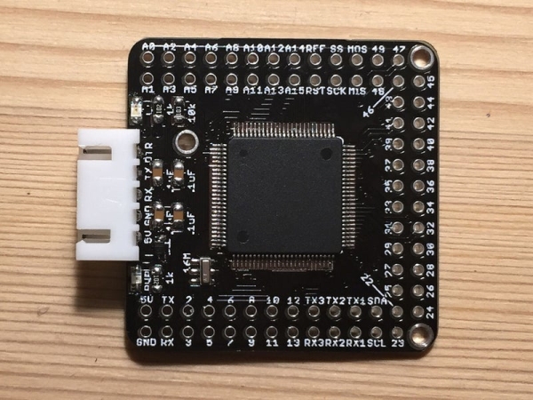
Specifications/features of the board layout:
- Total component count on board is 12.
- Board dimension is 38.1mm x 38.1mm.
- Connector pins to match CP2102 module.
- All digital pins and analog pins arranged in sequential order.
- Mounting holes.
- 4-layer PCB (failed attempt to route the traces in 2-layer).
Step 3: PCB Production: Revision I
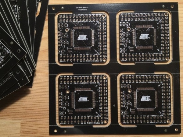
PCB’s were made by a manufacture found on China’s www.taobao.com; the cost for 4-layer PCB was 300RMB (45USD) excluding shipping for 10 pieces of 10cm x 10cm board (total of 48 “Naked Mega” produced, with panelizing and extras boards giving by the manufacture), production time was 6 days.
The leaded HASL process was selected for surface finish, this finish is not very flat, thus silkscreen (text and logo…etc.) wasn’t pretty; next revision will probably try Electroless Nickel Immersion Gold (ENIG) as the surface finish, cost would be 400RMB (60USD) for the same order.
Step 4: Solder Components: Revision I
Step 5: Upload Bootloader
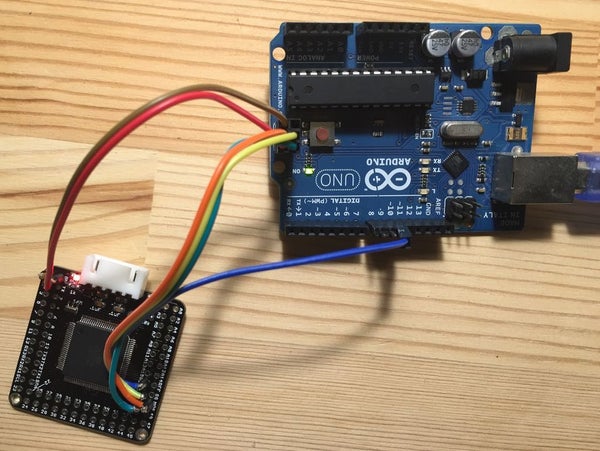
Used an Arduino Uno to upload bootloader onto the ATmega2560 chip, connections:
- Arduino UNO SS (D10) -> Naked Mega Reset/RST pin.
- Arduino UNO MOSI (D11) -> Naked Mega MOSI (D51).
- Arduino UNO MISO (D12) -> Naked Mega MISO (D50).
- Arduino UNO SCK (D13) -> Naked Mega SCK (D52).
- Arduino UNO VCC/5V -> Naked Mega 5V.
- Arduino UNO GND -> Naked Mega GND.
Downloaded Mr. Nick Gammon’s Atmega_Board_Programmer, and upload bootlaoder to chip using Serial Monitor of Arduino IDE according to instructions.
Step 6: Upload Sketch
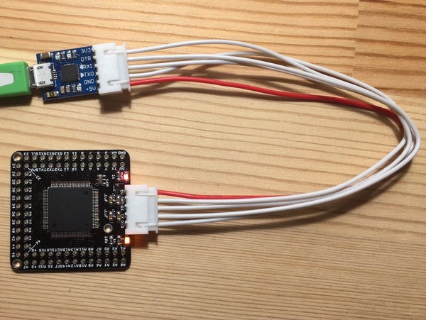
If the driver for CP2102 was installed, when connected the Naked Mega can be programmed like an original Arduino Mega 2560.
Read more: DIY Bare Minimum Arduino Mega 2560