
Summary of DIY Arduino Smart Digital Scale | ESP8266 + HX711
This article details a DIY digital scale project using an ESP8266 microcontroller, a 5kg load cell, and an HX711 ADC. The device features WiFi connectivity for cloud data transmission and includes an OLED display. It supports customization for object counting or volume calculation. The guide covers necessary skills like 3D printing and soldering, provides circuit diagrams, PCB ordering instructions via JLCPCB, 3D printable case files, assembly steps, and Arduino code with calibration parameters.
Parts used in the Digital Scale Project:
- ESP8266 (NodeMCU 1.0)
- OLED 1.3 inch i2C display
- Load Cell (5kg example)
- HX711 ADC to i2C converter
- 3D Printer
- Wires/Jumper wires
- Custom PCB (JLCPCB order)
- Gerber, BOM, and Pick & Place Files
- 3D Printed Case
- 3D Printed Plate
- Button panel
- Resistors and transistors (via BOM file)
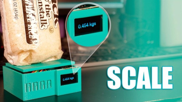
Hello to everyone, today I am here to show you a very insteresting project that I was working on for a while, it consists on a digital scale using the ESP-12S microcontroller plus a load cell and it HX711 wheatstone bridge to i2c converter, it is capable to measure weight precisely in the spectrum of grams, the sensor I am using is limited to 5Kg but you can use one for smaller or bigger weights.
As you can noticed, I am using the ESP8266 so it has WiFi capabilities that let me in the future send the measure data to the cloud.
The code can be modified to allow the scale to count objects, calculate liquid volume or what you imagine to do with force measuring.
Here I leave you a tutorial with all the information so you can make your own version.If you are a visual learner I know that a video worth more than 1000 words, so here is a Tutorial video. (I am a Spanish speaker, so please consider turning on English subtitles):
Step 1: Skills Required:

This project may seem difficult or very complex, but it is definitely not completely, since you will have all the guidance for the construction, it was difficult for me to design it to make life a little easier for you. Any conceptual doubt, you are free to ask it without problems.
- You should have an understanding of:
- 3D Printing (Optional for the case).
- Arduino programming (I give you the code).
- Soldering through hole components.
Step 2: Components and Parts List
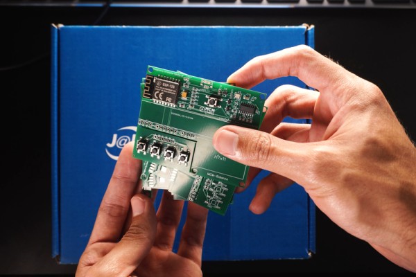
The Electronics discrete components as resistors and transistors will be attached in a BOM file attached here.
?Materials to build it without PCB:
?Materials to build it wit custom PCB:
- Custom JLCPCB PCBA order.
- Gerber File, BOM File, Pick & Place File (Free, just put 0 in the charge box).
- 3D Parts STL.
- OLED 1.3″ i2C display.
- Load Cell (ej 5kg) with Hx711 ADC to i2C
- 3D Printer
- Wires
Step 3: Circuit Diagrama and Schematic
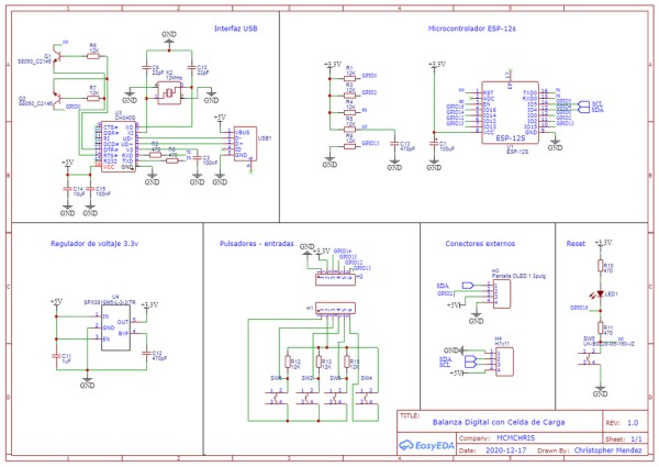
Here is the Circuit Diagram of our project:
It has all the internal conections of the circuit that will us allow to create the PCB design later.
I also attached the PDF of the Schematics so you can see it better.
Step 4: PCB Design and Ordering
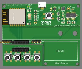
For the implementation of a good project we need a reliable assembly for the circuit that makes it up, and there is no better way to do it than with a good PCB.
I suggest JLCPCB:
$2 for 1-4 Layer PCBs⚡, Get SMT Coupons?
Step 5: 3D Design & Parts
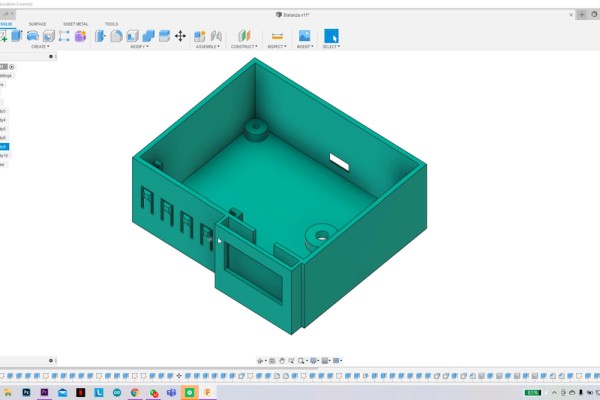
Here you have the STL files for the 3D parts of the project.
- Case.
- Plate
Step 6: Assambling the Whole Project

- Insert the PCB on the 3D printed case.
- Fix the load cell.
- Wire up everything with jumper wires.
- Glue the button panel.
- Place and wire the OLED display.
- Fix the plate of the scale and close the case with it.
Step 7: Code and Programming the ESP8266 Microcontroller
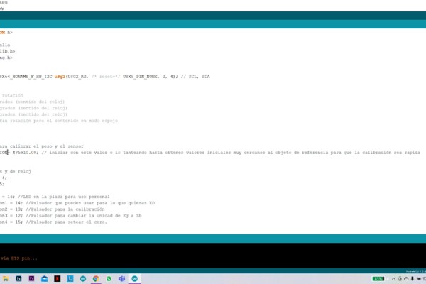
Download the CODE here for FREE (just insert 0 in the charge box).
Install the Hx711 Library and Ug2lib attached.
After you have opened the code in your Arduino IDE verify:
- That line 26 has: float CALIBRACION = 475910.00;
- That line 97 is commented://CALIBRACION = eeGetInt(addr);
- This let us firstly to set a calibration parameter that would next be tuned to get the right measurements.
- Select the NodeMCU 1.0 board. and the right port after connecting the main board of the project to your PC USB port.
- Upload the code.
- The scale need to be calibrated, see next step.
Source: DIY Arduino Smart Digital Scale | ESP8266 + HX711
-
What microcontroller is used in this project?
The project uses an ESP8266 microcontroller which provides WiFi capabilities. -
How much weight can the sensor measure?
The specific sensor used is limited to 5Kg, though smaller or larger weights can be used. -
Can I build this without a custom PCB?
Yes, you can build it without a PCB using discrete components attached to a BOM file, wires, and a 3D printer. -
What skills are required to construct this project?
You need an understanding of 3D printing, Arduino programming, and soldering through-hole components. -
Where can I download the Gerber and BOM files?
The files are available for free download to order a PCB from manufacturers like JLCPCB. -
How do I calibrate the scale after uploading the code?
You must verify line 26 has the calibration float value and ensure line 97 is commented out before uploading. -
What libraries are needed for the code?
You need to install the Hx711 Library and Ug2lib attached to the project resources. -
Can the code be modified for other functions?
Yes, the code can be modified to count objects or calculate liquid volume based on force measurement.
