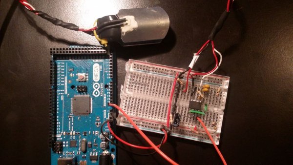
So I mentioned in an earlier Instructable that I am a teaching assistant (TA) for an introductory engineering course for biomedical engineering majors at Vanderbilt University. My main task as a TA is to re-write a few laboratory exercises that the students will be performed during the class. One of the laboratory exercises was to implement a simple circuit to measure the someone’s heart rate using photoplethysmography.
As blood is pumped through the body, the volume of blood in extremities such as your fingers increases and decreases with the pumping of the heart. The change in blood volume in the finger tips can be detected by shining a light through the finger and detecting the amount of light that passes through the finger using a photodiode. A photodiode is semiconductor that produces a current proportional to the amount of light that hits it. So when the blood volume in the fingers increases, less light is getting through the finger and hitting the photodiode.
The current produced by the photodiode is converted to a voltage by an amplifier and read by the Arduino. Here we go! I hope you enjoy reading and building!
Step 1: Gather Your Tools
You will need
1 x Arduino (of course)
1 x General Purpose Op Amp
5 x Resistors
3 x Capacitors
1 x Photodiode
1 x IR LED
For the general purpose op amp, I used an MCP6002 which can be purchased from any major electronics distributor such as DigiKey.com, Mouser.com, or Newark.com. I purchased mine from Newark. I liked this op amp because it is single supply, meaning it only needs to be powered using ground (GND) and a positive voltage. It does not need a negative voltage supply like many other op amps. This enables it to be easily integrated with the Arduino which only runs on a positive supply. If you use a bipolar op amp, you have to make sure the op amp and Arduino are running on the same GND and positive supply. Do not connect the negative supply to the Arduino. You will fry something on it. I have done it before.
The resistor values that you will need are as follows:
3 x 1 MOhm resistors
1 x 10 kOhm resistor
1 x 1 kOhm resistor
The capacitor values that you will need are as follows:
1 x 10 nF
1 x 560 nF (I ended up using a 470 nF and 100 nF in parallel – which adds us to 570 nF – which is close enough)
For the photodiode and IR LED, the Bio-Instrumentation lab at Vanderbilt University made a few finger cuffs with integrated photodiode and IR LED, so we used those for the lab. You can purchase disposable finger cuffs online. You can make your own as well. You just need some sort of housing for the photodiode and IR LED to keep them really steady on someone’s finger.
Step 2: Summary of Operation
As the heart pumps blood through the body the volume of blood in extremities such as the fingers increases and decreases. We can detect the change in blood volume in the fingertips by shining a light through the finger and detecting the amount of light that passes through the finger using a photodiode.
Step 3: Circuit Diagram
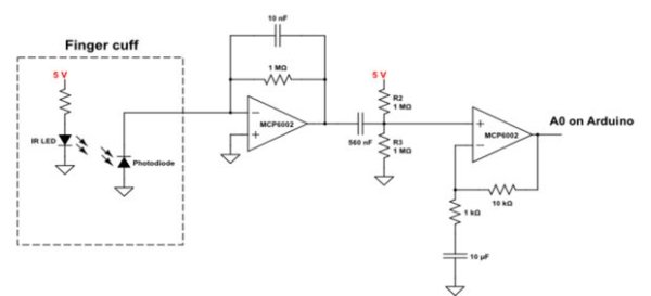
We will be creating the circuit depicted in the corresponding image. The circuit has three main parts:
- Finger cuff
- Transimpedance stage
- High-pass filter
- AC gain-stage
I will explain these various parts in the next sections.
Step 4: Finger Cuff
As I stated before, the finger cuff has a photodiode (I don’t know the part number) and IR LED integrated into it. Both components have wires that connect them to the Arduino.
For more detail: DIY Arduino Pulse Sensor


