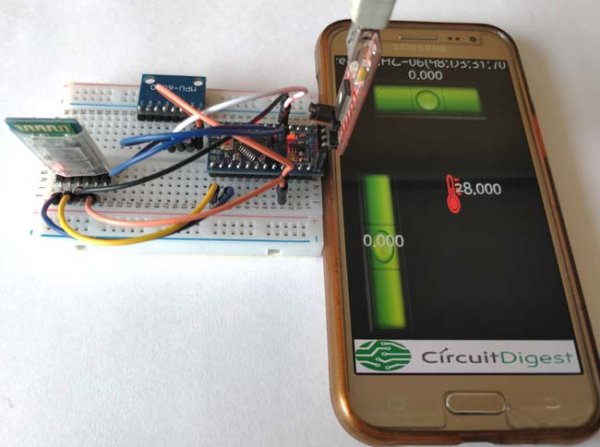
The MPU6050 is an IC 3-axis accelerometer and a 3-axis gyroscope combined into one unit. It also houses a temperature sensor and a DCM to perform a complex task. The MPU6050 is commonly used in building Drone and other remote robots like a self-balancing robot. In this project we will learn how to use the MPU6050 is built an Inclinometer or Spirit Leveller. As we know an inclinometer is used to check if a surface is perfectly leveled or not, they are available either as sprit bubble ones or as digital meters. In this project, we are going to build a Digital Inclinometer which can be monitored using an Android application. The reason for using a remote display like a mobile phone is that we can monitor the values from MPU6050 without having to look at the hardware, this would come very handy when the MPU6050 is placed on a drone or some other inaccessible locations.
Materials Required:
- Arduino Pro-mini (5V)
- MPU6050 Gyro Sensor
- HC-05 or HC-06 Bluetooth module
- FTDI board
- Breadboard
- Connecting wires
- Smart Phone
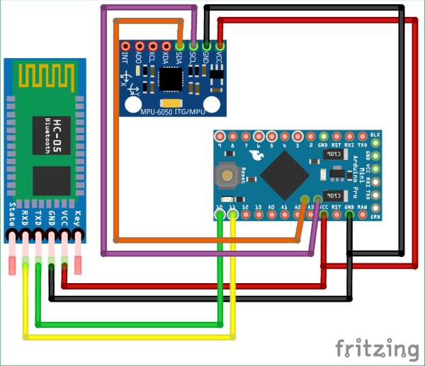
Circuit Diagram:
The complete circuit diagram for this Arduino Tilt Sensor Project is shown below. It just has only three components and can be easily built over the breadboard.
The MPU6050 communicates with the help of I2C and hence the SDA pin is connected to the A4 pin of Arduino which is the SDA pin and the SCL pin is connected to the A5 pin of Arduino. The HC-06 Bluetooth Module works with the help of Serial communication hence the Rx pin of Bluetooth is connected to pin D11 and the Tx pin of Bluetooth is connected to pin D10 of the Arduino. These pin D10 and D11 will be configured as Serial pin by programming the Arduino. The HC-05 module and the MSP6050 module operates on +5V and hence they are powered by the Vcc pin of the Arduino as shown above.
I used some breadboard connecting wires and built the set-up over a small breadboard. Once the connections are done my board looks like this below.
Powering your setup:
You can either power your circuit through the FTDI programming board as I have did, or use a 9V battery or 12V adapter and connect it to the Raw pin of the Arduino pro mini. The Arduino Pro-mini has an in-built voltage regulator which would convert this external voltage regulated +5V.
Programming your Arduino:
Once the hardware is ready, we can start programming our Arduino. As always the complete code for this project can be found at the bottom of this page. But to understand the project better I have broken the code to small chinks and explained them as steps below.
The first step would be interfacing the MPU6050 with Arduino. For this project we are going to use the library developed by Korneliusz which can be downloaded from link below
MPU6050 Liberty – Korneliusz Jarzebski
Download the ZIP file and add it to your Arduino IDE. Then head on to File->Examples->Arduino_MPU6050_Master -> MPU6050_gyro_pitch_roll_yaw. This will open the example program that uses the library that we just downloaded. So click on upload and wait for the program to be uploaded to your Arduino Pro mini. Once that is done open your serial monitor and set your baud rate to 115200 and check if you are getting the following.
Read more: DIY Arduino Inclinometer using MPU6050