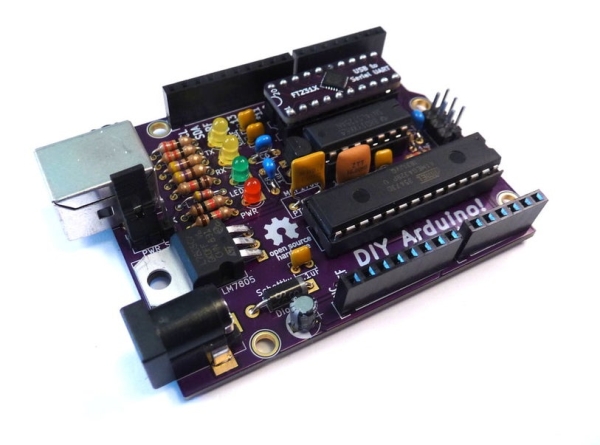
Summary of DIY Arduino-Compatible Clone
This article guides beginners on building a DIY Arduino-compatible clone using through-hole components to avoid difficult surface-mount soldering. The project utilizes an FTDI chip adapted for through-hole use, an Atmega328 microcontroller, and various passive components like resistors, capacitors, and diodes. Designed in Open Source KiCad, the build allows users to modify the design while keeping assembly accessible.
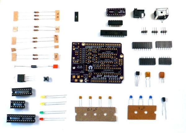
Parts used in the DIY Arduino-Compatible Clone:
- Through-hole FTDI chip (surface mount package converted)
- Atmega 328 microcontroller
- Arduino circuit board
- FTDI circuit board
- Soldering iron
- Solder
- Wire nippers
- Desoldering braid
- Resistors (10K, 22 ohm, 470 ohm, 4.7K, 1K)
- Diode
- 7805 Voltage Regulator (5V)
- IC Sockets
- Reset Button
- LEDs (Yellow, Green, Red)
- Ceramic Capacitors (0.1uF, 1uF)
- Electrolytic Capacitor (0.33 uF)
The Arduino is the ultimate tool in the Maker’s arsenal. You should be able to build your own! In the early days of the project, circa 2005, the design was all through-hole parts and communication was via a RS232 serial cable. The files are still available, so you can make your own, and I have, but not many computers have the older serial ports.
The Arduino USB version followed shortly, and probably contributed greatly to the project’s success because it allowed easy connection and communication. It did, however come at a cost: the FTDI communication chip only came in a surface mount package. Plans are still available for it as well, but surface mount soldering is beyond most beginners.
Newer Arduino boards use 32U4 chips with built in USB (Leonardo), or separate Atmel chips for USB (UNO), both which still leave us in surface mount territory. At one point there was “TAD” from Dangerous Devices that used a through hole PIC to do USB, but I can’t find anything left on the web of them.
So here we are. I firmly believe a beginner, like a Jedi Knight, should be able to build their own Arduino (light sabre). “An elegent weapon from a more civilize age”. My solution: make a through-hole FTDI chip using a surface mount package! That allows me to do the surface mount, and offer the remaining project as DIY through-hole! I also designed it in Open Source KiCad, so you can study the design files, modify them, and spin your own version.
If you think this is a stupid idea, or love surface mount soldering, check out my Leonardo Clone, otherwise, read on . . .
Step 1: Parts and Supplies
The full bill of materials is located at https://github.com/aspro648/Arduino/tree/master/D…
The unique parts of this are the circuit boards, one for the Arduino, and one for the FTDI chip. You can have OSH Park make them for you, or use the design files with your favorite board house.
A kit for this project is available on Tindie.com. Purchasing the kit will save you the time and expense of ordering from several different vendors and avoid the minimum PCB order premium. It will also provide you a tested surface-mounted FDTI through-hole chip as well a pre-flashed Atmega.
Tools and Supplies:
For my workshops, I use SparkFun’s Beginner’s ToolKit which has most of what you need:
- Soldering iron.
- Solder
- Wire nippers
- Desoldering braid (hopefully not needed, but you never know).
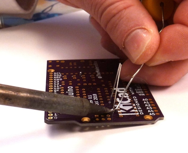
Step 2: Ladies and Gentlemen, Start Your Irons
I’m not going to try and teach you soldering. Here are a couple of my favorite videos that show it much better than I can:
In general:
- Find the location on the PCB using the silk screen markings.
- Bend the component leads to fit the foot print.
- Solder the leads.
- Trim the leads
Step 3: Resistors
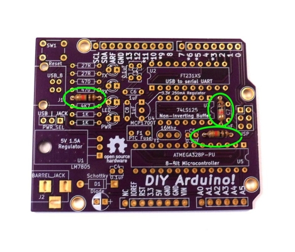
Let’s start with resistors since they are the most plentiful, lowest seating, and easiest to solder. They are more heat resistant and will give you a chance to brush up on your technique. They also have no polarity, so you can put them in either way.
- Start with the three 10K ohm (brown – black – orange -gold), which are in a couple of places on the board (see picture). These are “pull-up” resistors that keep the signal at 5V unless they are actively pulled low.
- Pair of 22 ohm (red – red – black – gold) are in the upper left corner. These are part of the USB communication circuit.
- Pair of 470 ohm (Yellow, Violet, Brown, Gold) are the next ones down. These are current limiting resistors for the RX/TX LEDs.
- Single 4.7K ohm (Yellow, Violet, Red, Gold). An odd-ball for the FTDI VCC signal.
- And finally, a pair of 1K ohm (Brown, Black, Red, Gold). These are current limiting resistors for the power and D13 LEDs (330 ohm would work, but I don’t like them too bright).
Step 4: Diode
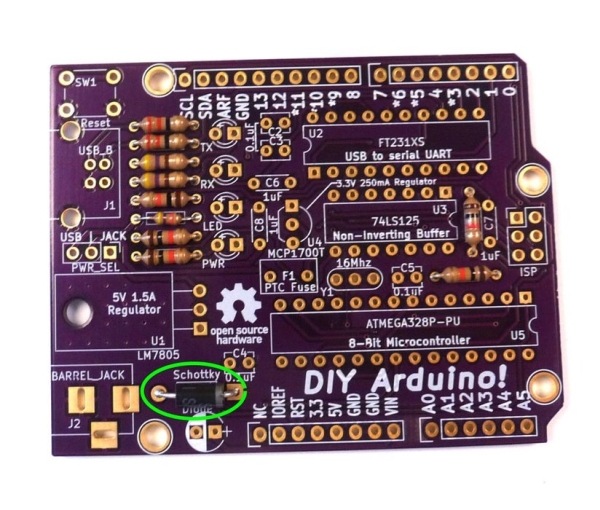
Next up we have the diode which protects the circuit from reverse current from power jack. Most, but not all components will react poorly to reverse polarity.
It has a polarity which is marked by a silver band on one end.
Match it with the silk screen marking and solder in place.
Step 5: Voltage Regulator (5V)

There are two voltage regulators, and the main one is a 7805 which will regulate twelve volts from the jack down to 5 volts that the Atmega 328 needs. There are large copper features on the printed circuit board to help dissipate heat. Bend the leads so that the back touches the board with the hole aligned with the hole in part and solder in place.
Step 6: Sockets
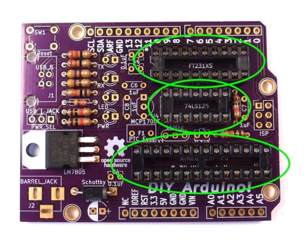
Sockets allow IC chips to be inserted and removed without soldering. I think of them as insurance because they are cheap and allow you to replace a blown chip or reorient the IC if put in backward. They have a divot in one end to show the direction of the chip, so match it to the silk screen. Solder two pins and then verify it is seated correctly before soldering the remaining pins.
Step 7: Button
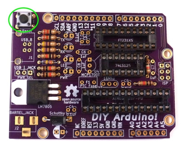
Arduino’s typically have a reset button to restart the chip if it hangs up or needs to restart. Yours is in the upper left corner. Press it in place and solder.
Step 8: LEDs
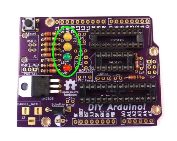
There are a number of LEDs to indicate status. LEDs have a polarity. The long leg is the anode, or positive, and goes in the round pad with the “+” next to it. The short leg is the cathode, or negative, and goes in the square pad.
The color is arbitrary, but I typically use:
- Yellow for RX/TX which blink when the chip is communicating or being programmed.
- Green for the the D13 LED which can be used to by the program to indicate events.
- Red to show 5 volt power is available either via USB or the power jack.
Step 9: Ceramic Capacitors
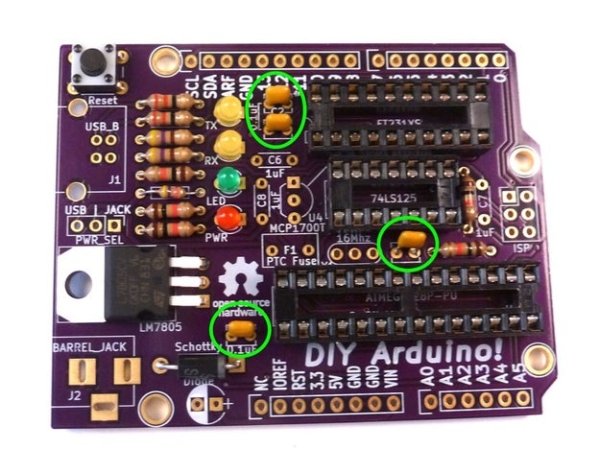
Ceramic capacitors have no polarity.
Power smoothing capacitors are typically used to remove transients from the power supply to chips. The values are typically specified in the component’s data sheet.
Each IC chip in our design has a 0.1uF capacitor for power smoothing.
There are two 1uF capacitors for smoothing power around the 3.3 volt regulator.
Additionally, there is a 1uF capacitor that helps with the timing of the software reset function.
Step 10: Electrolytic Capacitors
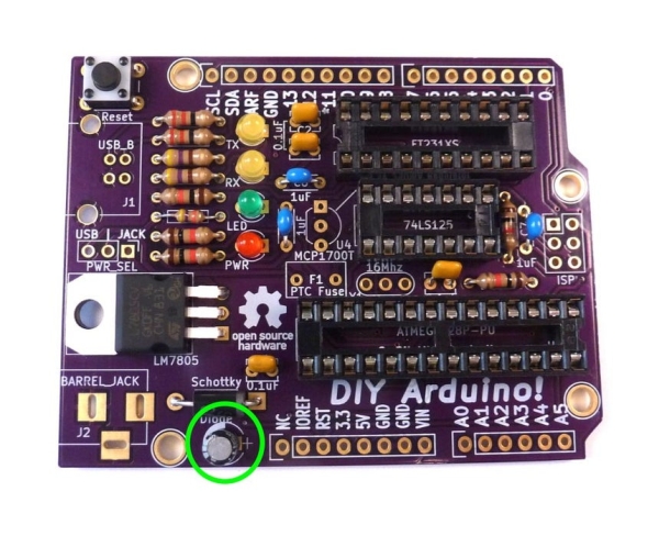
Electrolytic Capacitors do have a polarity which must be observed. They typically come in larger values than ceramic capacitors, but in this case we have 0.33 uF capacitor for power smoothing around the 7805 regulator.
The long leg of the device is positive and goes in the square pad marked “+”. These tend to go “pop” if put in backward, so get it right or you will need a replacement.
Source: DIY Arduino-Compatible Clone
- Why was this specific through-hole design created?
To allow beginners to build their own Arduino without needing surface mount soldering skills. - What tool is recommended for learning soldering techniques?
The SparkFun Beginner's ToolKit contains most of what is needed for workshops. - How can you identify the correct orientation for a diode?
Match the silver band marking on the component with the silk screen marking on the board. - What is the purpose of the 7805 voltage regulator?
It regulates twelve volts from the power jack down to 5 volts required by the Atmega 328. - Why are IC sockets used in this project?
They act as insurance to allow chips to be inserted, removed, or replaced without soldering. - How do you determine the polarity of an LED?
The long leg is the anode (positive) and goes in the round pad, while the short leg is the cathode (negative). - Which capacitor values are used for power smoothing around the 3.3 volt regulator?
Two 1uF capacitors are used for smoothing power around the 3.3 volt regulator. - What happens if an electrolytic capacitor is installed backward?
The device may pop, requiring a replacement. - Can users modify the design files for this project?
Yes, the design is in Open Source KiCad so users can study, modify, and spin their own versions. - What color LEDs are suggested for RX/TX status indication?
Yellow LEDs are typically used for RX/TX which blink during communication or programming.