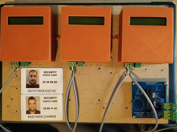
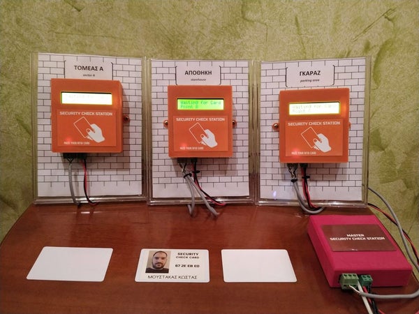
In this DIY guide I will show you how to make your own security check system based on Arduino!
You can use this system in areas with security guards (e.g. warehouses, malls, open areas). Every guard will have a personal RFID card with a unique ID number. When a security guard pass his cards over the Check point station – the ID and the current time/date will be stored inside controller memory (EEPROM). The security guard inside the “Control Room” can read the report of all check point stations with only one click!
This project started out as a Bachelor’s thesis by me – John Vasilakis (supervised by Grigoris Tziallas) – Electronic Engineering Department of Stereas Elladas University. We are supporting the open hardware – software community so this project will be marked as an open-source. Before share/copy/change anything of below guide, make sure to read and agree with the CC BY-NC-SA licence agreement!
We used the RFID technology to read scanned card and the RS485 electrical data bus protocol for communication. In this project I decided to make my own PCB that is based on Arduino UNO microcontroller – Atmega328p.
We can have up to 254 slave-check point stations and one master station in the RS485 data bus. The master station is communicating with one computer in security room via serial USB port. We will describe the communication protocol in the following steps!
Let’s get started.
~Project link can be found here:
https://www.ardumotive.com/arduino-security-check-…
Video presentation:
Step 1: What You Will Need – Hardware Part List
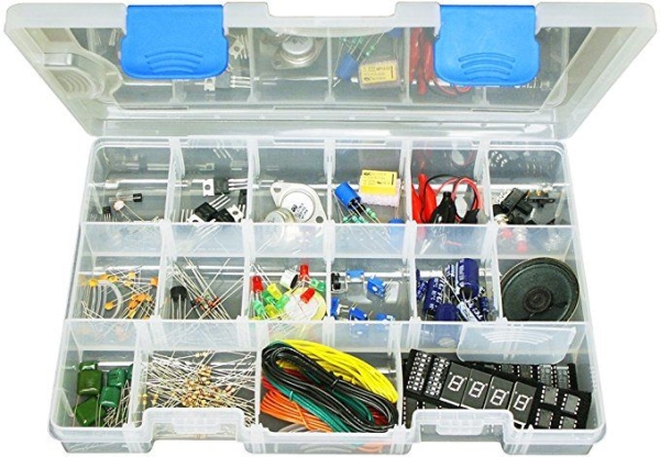
For Master Station you will need:
- Our custom PCB circuit
- Atmega328 (with Arduino UNO bootloader)
- 28 dip socket
- 16 MHz crystal oscillator
- 2×22 pF capacitors
- 1x100nF ceramic capacitor
- 1x10uF Electrolytic Capacitor
- 1x10K resistor
- Screw terminal 2P 2.54mm
- 2xPin Header 1×5 Female 2.54mm
—-> Or use an Arduino board with breadboard
~Power by 5V power adapter
For every Slave – Sensor Station you will need:
- Our custom PCB circuit
- Atmega328 (with Arduino UNO bootloader)
- 28 dip socket
- 16 MHz crystal oscillator
- 2×22 pF capacitors
- 1x100nF ceramic capacitor
- 1x10uF Electrolytic Capacitor
- 1x10K resistor
- Screw terminal 2P 2.54mm
- 2xPin Header 1×5 Female 2.54mm
—-> Or use an Arduino board with breadboard
- SN75176 Transceiver RS485
- Display 16×2 Character LCD – 5V
- Trimmer 20kOhm
- RFID MFRC-522 Module
- DS1307 IC RTC
- 32.768 KHz Crystal
- Coin Cell Battery Holder (for CR2032 type batteries)
- buzzer
~Power by 5V power adapter
*You will also need a TTL to USB module or an Arduino UNO board for the programming procedure, and then use it for USB communication for Master Station.
Step 2: The Circuit – Electronic and PCB Schematic
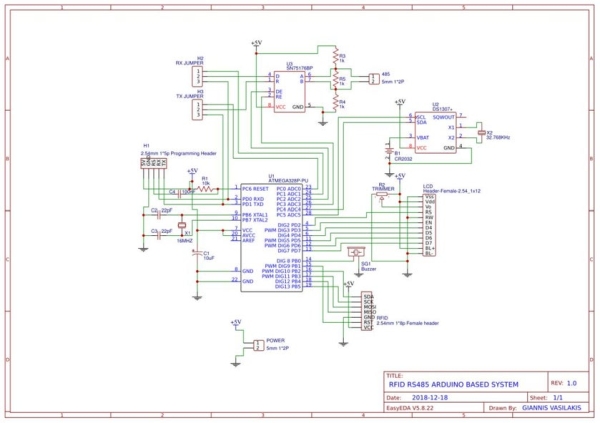
Find the electronic and pcb schematic at link below:
https://easyeda.com/mi.vasilakis/RFID-RS485-ARDUIN…
You can make any changes you want!
We used the JLCPCB for $2 PCB Fabrication & 2-day Build Time, the quality is really good, check the below photo of our pcb board. JLCPCB it will not charge you for any color selection for your pcb board! Enter here to produce your PCB board!
Step 3: Arduino Connection Pins
LCD
- RS pin to Arduino Pin 2
- EN pin to Arduino Pin 3
- D4 pin to Arduino Pin 4
- D5 pin to Arduino Pin 5
- D6 pin to Arduino Pin 6
- D7 pin to Arduino Pin 7
RFID
- SDA pin to Arduino Pin 10
- SCL pin to Arduino Pin 13
- MOSI pin to Arduino Pin 11
- MISO pin to Arduino Pin 12
- RST pin to Arduino Pin 9
RTC
- SDA pin to Arduino Pin A4
- SCL pin to Arduino Pin A5
SN75176
- RE pin to Arduino Pin A3
- DE pin to Arduino Pin A2
- R pin to Arduino Pin A0
- D pin to Arduino Pin A1
Buzzer to Arduino Pin 8
Step 4: Communication Protocol
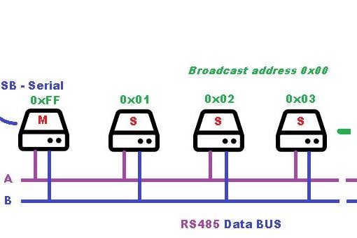
*See the attached images.
Step 5: The Code
Connect your circuit with the TTL to USB module with 5 cables to the programming header. The pins RX and TX must be cross-connected.
NOTE: If you are using the Arduino UNO board make sure to remove the ATmega328 IC from it first and connect the headers RX to RX and TX to TX pins of the board. The RS pin must be connected to Arduino UNO reset pin.
————-CONFIGURATION—————–
Master
Code for the master station unit. The “Master Station” is responsible for the communication between “Slave stations” via RS485 data bus. It also communicate via serial port with the software that is running to “control room” computer.
Slave
Code for the slave station units. Every “Slave Station” – check point unit has a unique address. Edit the variable “PORT” (line 25) with hex value of unit address – value from 01 to FE (total of 254 stations). Also change the “name” of the current station by editing the variable “point” at line 24. Every check point can store to EEPROM memory up to 10 card IDs. If the security card exist, the ID and time-stamp will be saved to EEPROM memory.
Download the code from here and open it with Arduino IDE. Inside you will also find all library files.
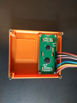
Step 6: 3D Parts
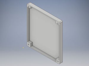
Download and print the case of the master and slave stations with your 3D printer!
Step 7: Windows Software
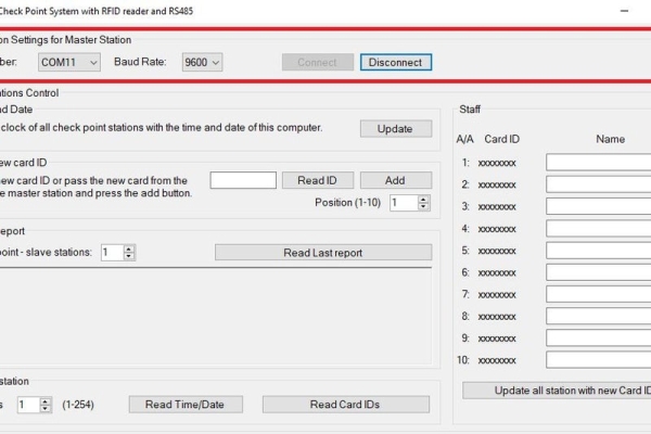
In this section we will describe the operation of the software that will run in the “control” room computer.
- First, you need to connect with master station via serial port.
- Once logged in we will update the time and date of all stations based on the clock of the computer.
- We have the option of entering the cardholder’s name in our staff list. To do this, pass a card over the RFID (of master station) to read the ID and after the ‘beep’ sound click the “Read ID” button, select index position (from 1 to 10) and click the “Add ” button. The new ID will be added to staff panel, there you can add a name of the employee. Now click on “Update Stations with Card IDs” button, now all stations are updated with new cards.
- The report given by the devices since the card last passed. The total number of control stations indicates how many devices we have. We use 3 devices in our example. Clicking on the last check status report will look at the report that our devices gave us. For example: Station 1 replied that the E0 BD 74 AE card passed on 26/2/2019 at 19:13.
- Finally, we can read the time and date or the card table of each device.
Step 8: Well Done!
I hope you liked this, let me know in the comments!!!
Source: Security Check RFID System Based on Arduino and RS485 Data Bus