Ever wanted to make your home automated? Wanted to control the lights, fan, and other appliances from your smartphone? Or wanted a tutorial about connected devices and getting started with them? Our DIY Android Home Automation project will show you how to make your home automated using an Android smartphone. This requires no experience with Android programming at all, and a free application is included for you to develop. Using this Android application you will be able to control your lights, air conditioning, and door locks all from your smartphone. This system Bluetooth to connect with your device and control the various appliances in your home. Have fun with this DIY hacking tutorial!

Required Materials
Hardware :
- Arduino / Arduino Clone or make your own custom Arduino board with this tutorial.
- A 5v TTL -UART Bluetooth module like: JY-MCU BT_BOARD (Cheaper) or Bluesmirf Gold/Silver.
- Five 5V SPDT relays like: 5V relay.
- Prototype board or breadboard.
- Connecting wires.
Software :
- Arduino IDE
- Eclipse for Android programming (optional, not required). For instructions on installing and setting up the environment: How to install android and eclipse, And tutorials to learn Android programming even though you don’t require it for this project.
How Does it Work?
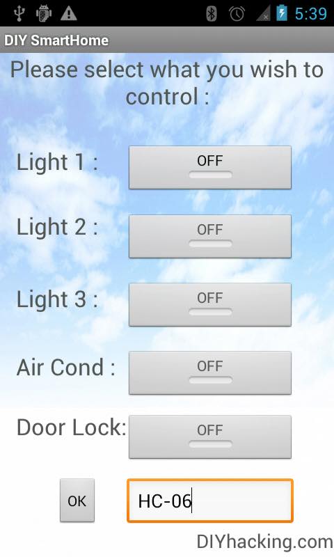
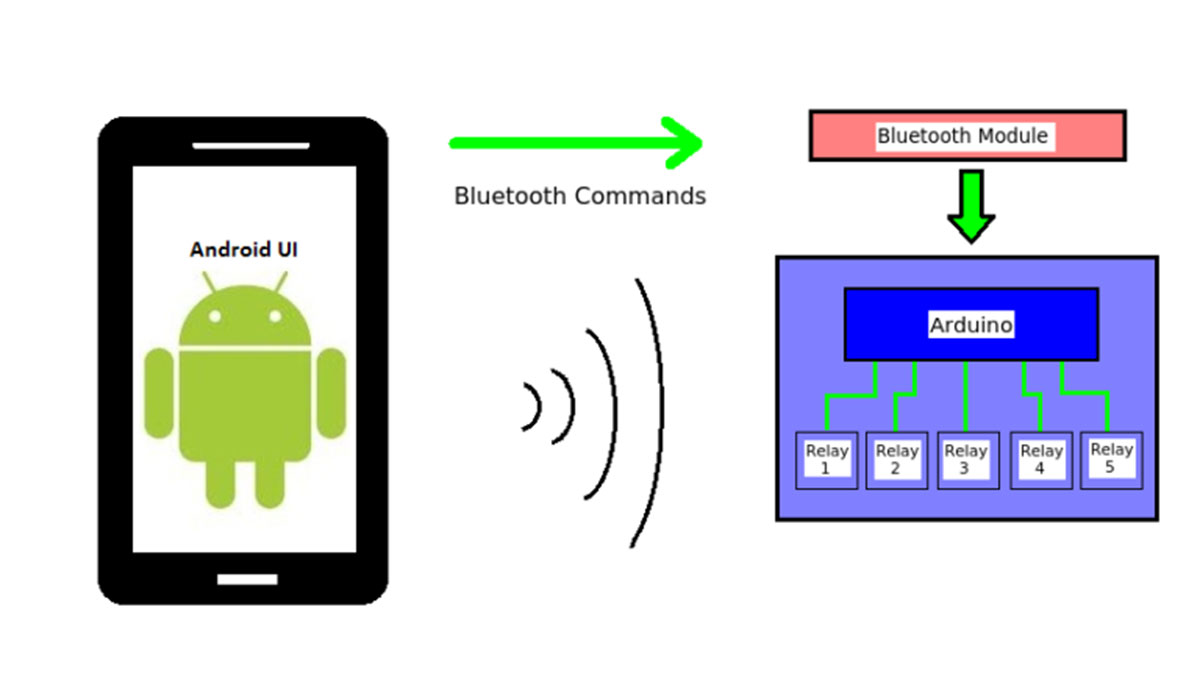
The DIY Android Home Automation project comes with a free application called “DIY SmartHome”. This application controls the various appliances connected to your Arduino and relays. When the toggle buttons on the application are pressed, corresponding Bluetooth signals are sent from your Android phone to the Bluetooth module you have hooked up to your Arduino. The Arduino finds out which signal was sent and compares it to the predefined signals assigned for each appliance. When it identifies that signal, the Arduino activates the relay hooked up to its digital pin by passing 5V through it. Thus the relay is switched ON and the corresponding appliance connected to the relay is turned ON as well. To switch it OFF, Arduino passes a 0V or logic low to its digital pin.

Setting Up the Connections for the DIY Android Home Automation Project

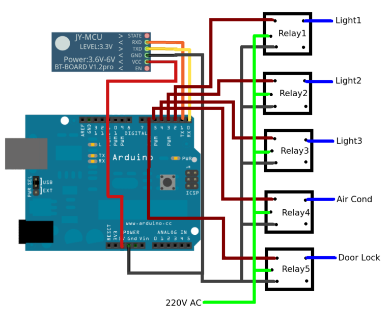
The connection diagram for Arduino is as shown. For setting up this system, wiring connections have to be made between the Arduino and Bluetooth module and also with the relays. Here, the Bluetooth Module’s Tx is connected to Arduino Rx (digital pin 0) and the module’s Rx to Arduino Tx (digital pin 1). 5V and GND of the module are connected to the Arduino’s 5V and GND.
The relay your using is SPDT, it has 5 pins on the underside. As shown above, here pins 1 and 3are the coil pins. 1 is connected to the Arduino digital pin and 3 is connected to Arduino GND. 2 is the common contact in the relay to which you have to connect the power for your appliance (AC 230V), and 4 is the pin to which you have to connect your appliance wire.
Connecting Your Appliance to the Relay
In a normal SPDT relay, whose pin out is shown in the above step, pins 2 and 4 act identical to the two terminals of a switch. When a digital HIGH voltage is applied from the Arduino to the relay, the switch turns ON, when the voltage is withdrawn, it turns OFF. You can attach this system you made to a normal switchboard by extending the wires from behind the switches in the board to your relay. As seen in the connection diagram in the above step, you have to connect a power AC line to the common terminal of all the relays. Then, you have to extend the wires from behind the switchboard of the corresponding lights/lamps you wish to control. Each of these wires is connected to the “NO”(Normally Open) terminal of the relays (pin no 4 in step no 1’s relay pin out diagram). NOTE: If you wish to control door locks, you may use door lock solenoids, which can be purchased and connected to your system and turned ON/OFF using the same way. The picture below shows how you can attach the system to your switchboard (keep in mind, this is just to show you the arrangement, it is not the original system being described here):
Read More: DIY Android Home Automation With Free Smartphone Application
