Summary of DIY Android Home Automation Box
This article details a prototype Android-controlled home automation box. Users can toggle outlets via an app or voice commands using Bluetooth. The project involves modifying an enclosure, mounting AC sockets, and wiring a relay circuit powered by an external supply. The author notes this is an early version with safety warnings regarding exposed AC lines and promises a more thorough update later.
Parts used in the DIY Android Home Automation Box:
- Android Phone & App
- Arduino UNO (a clone works fine)
- Low Power/ Switching Power Supply
- Dot Matrix Solderless Breadboard
- HC-05 Serial Bluetooth Module
- 2N3904 NPN Transistor (5x)
- 2.2k Ohm Resistor 1/4 (5x)
- 6V Relays (5x)
- Jumper Cables
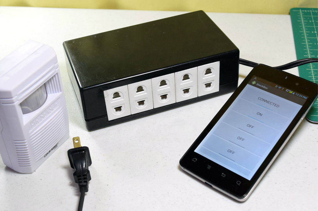
Here’s a little show and tell of my Android controlled home automation box. It’s a small extension box that’s controlled by an Android smartphone. You can turn the individual outlets on by tapping a button from the app or use the speech recognition app, found from my previous tutorial. I’ve teamed up with my friends and built a custom app for out home automation prototype project. My former classmate/ fellow ible member “treyes4” built something similar.
__________________
It’s just a prototype so don’t expect much from this version. I assure that next version would be explained more thoroughly.
________________
I’ll be gone for a while: I’ll be posting a video once I get back from the international trade and business competition hosted by FedEx (school related). I posted this guide early, since the home automation contest deadline is due today. There’s a lot of unexplained areas in this guide, without the prior knowledge, this project would be difficult to execute. Just ask questions below, I’ll answer them through my phone. Once I get back, I’ll edit and update this guide. Sorry for the inconvenience.
__________________
Step 1: Bill Of Materials
If your having trouble in finding them, I’m sure RadioShack has all of them. If you want to buy online try searching on Amazon or DealExtreme.
Thing that you’ll need:
– Android Phone & App
– Arduino UNO (a clone works fine)
– Low Power/ Switching Power Supply
– Dot Matrix Solderless Breadboard
– HC-05 Serial Bluetooth Module
– 2N3904 NPN Transistor (5x)
– 2.2k Ohm Resistor 1/4 (5x)
– 6V Relays (5x)
– Jumper Cables
Step 2: Find A Good Enclosure
I bought my enclosure from Alexan, a local electronics/ hobby store. This project is a prototype, the perfect enclosure would be an enclosure big enough to house an Arduino prototyping board and a small switching-PSU.
Step 3: Glue The Sockets Together
Align the outlets then use superglue to hold them temporarily. Hot glue can be used to strengthen the bond. After gluing, start to link a common rail. The linked rail work’s like a common ground although this is AC ~ so it’s not.
Step 4: Align & Measure The Sockets
Align the AC sockets together then acquire the dimensions of the array of sockets.
Step 5: Transfer The Measurements
Transfer your measurements by using a marker and ruler.
Step 6: Grind And Drill The Enclosure
Use your hacksaw or rotary tool to cut off the plastic that you’ve marked. Use a metal file to even out the edges.
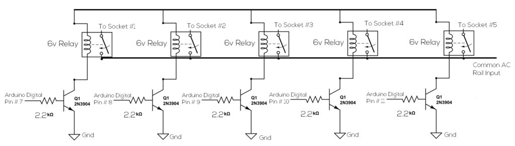
Step 7: Construct The Relay Circuit
I constructed my DIY relay circuit. Obviously this is a complete prototype, I used a perfboard for mounting my components on. This is dangerous, exposed AC line can cause death through electrocution. Before attempting this project, be sure you’re qualified to execute the task. My next version in the future would probably include solid state relays mounted on a custom PCB.
Step 8: Wire The PSU
The PSU will serve as your Relay and Arduino’s power supply. I bought mine from ebay.
Specs: 12v (1 Amp)
For more detail: DIY Android Home Automation Box
- How do I control the individual outlets?
You can turn the individual outlets on by tapping a button from the app or use the speech recognition app. - Can I use a clone Arduino instead of the original?
Yes, a clone of the Arduino UNO works fine for this project. - What power supply specifications are recommended?
The project uses a Low Power/ Switching Power Supply with specs of 12v at 1 Amp. - Is it safe to attempt this project without experience?
No, exposed AC line can cause death through electrocution, so you must be qualified to execute the task. - Where can I buy the required components?
You can find them at RadioShack, Amazon, or DealExtreme. - What material was used to mount the components?
A perfboard was used for mounting the components on the DIY relay circuit. - Does the guide include solid state relays?
No, this prototype uses standard relays; the next version will probably include solid state relays mounted on a custom PCB. - What tool should be used to cut the enclosure plastic?
You should use a hacksaw or rotary tool to cut off the marked plastic.