Let’s learn how to read a pushbutton using Arduino’s digital input! We’ll connect up a simple circuit using a solderless breadboard and use some simple Arduino code to control a single LED.
So far you’ve learned to control LEDs with code, which is one use for Arduino’s outputs. This lesson builds on outputs by adding an input. Your Arduino board can be programmed to listen to electrical signals and take actions based on those inputs. A pushbutton is one kind of switch, a mechanical device that connects or breaks a circuit.
To optionally build the physical circuit, gather up your Arduino Uno board, USB cable, solderless breadboard, an LED, resistors (one from 100-1K ohms and one 10K ohm), pushbutton, and breadboard wires.
You can follow along virtually using Tinkercad Circuits. You can even view this lesson from within Tinkercad (free login required)! Explore the sample circuit and build your own right next to it. Tinkercad Circuits is a free browser-based program that lets you build and simulate circuits. It’s perfect for learning, teaching, and prototyping.
Step 1: Build the Circuit
Explore the sample circuit embedded here by starting the simulation and testing the pushbutton. Remember that the breadboard rows are connected inside, so you can plug in components and wires to make quick temporary connections. You could load up a new Tinkercad Circuits window and build your own version of this circuit along side the sample.
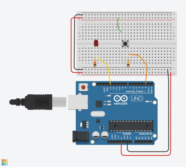
Identify the pushbutton, LED, two resistors, and wires connected to the Arduino in the Tinkercad Circuits workplane.
Drag an Arduino Uno and breadboard from the components panel to the workplane.
Connect breadboard power (+) and ground (-) rails to Arduino 5V and ground (GND), respectively, by clicking to create wires.
Extend power and ground rails to their respective buses on the opposite edge of the breadboard by creating a red wire between both power buses and a black wire between both ground buses.
Plug the LED into two different breadboard rows so that the cathode (negative, shorter leg) connects to one leg of a resistor (anywhere from 100-1K ohms is fine). The resistor can go in either orientation because resistors aren’t polarized, unlike LEDs, which must be connected in a certain way to function.
Connect other resistor leg to ground.
Wire up the LED anode (positive, longer leg) to Arduino pin 13.
Drag a pushbutton from the components panel to the center of your breadboard, and place it across the center column break so that its legs are plugged into four different breadboard rows.
Click to create a wire connecting one button leg to power.
Connect the diagonally opposite leg to Arduino digital pin 2.
Create and position a high value resistor (such as 10K) between that same button leg and ground.
Step 2: Pull-Down Resistor
Why do we need a resistor in order to read the switch?
At rest, the two sides of this switch are not connected to one another. You can hover over the switch pins to see their Terminal labels. The switch is normally open, meaning at rest, Terminal 12 and Terminal 22 are not connected to Terminal 11 and Terminal 21 of the pushbutton. Arduino pin 2 is connected through a beefy 10K resistor to ground. When the button is pressed, the switch leads are connected, which allows pin 2 to be connected to 5V power, with no resistor. Since electricity takes the path of least resistance, the pin will sense the connection to power strongly, and ignore the weak (10K) connection to ground.
But when no other signal is present (when the switch isn’t being pressed), that weak connection to ground is all the pin can sense. So the resistor is “pulling the pin down” to ground, and so it’s called a pull-down resistor. Without one, pin 2 would be not connected to anything until the button is pressed. This is called “floating”, and can result in random noise from static electricity and electromagnetic interference. Similarly a resistor can be used to tie a pin to power, which is called a pull-up resistor.
Add a multimeter component to the workplane and wire it up to Arduino pin 2 and ground.
Click Start Simulation and click to press/hold the pushbutton to observe the digital signal being picked up by pin 2.
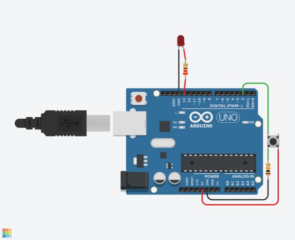
To better understand what’s going on, it’s useful to also take a look at a free-wired version of the sample circuit, pictured here.
Step 3: Code With Blocks
Let’s use the code blocks editor to listen to the pushbutton, then make a decision about whether to light up an LED based on the pushbutton’s state: pressed or not pressed.
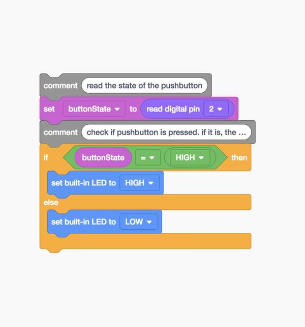
Click the “Code” button to open the code editor. Play the GIF above to see the program built in blocks.
Click on the Variables category in the code editor. Create a new variable called buttonState.
Drag out a “set” block.
We’ll store the state of our pushbutton to our variable buttonState. Click on the Input block category, drag out the the “read digital pin” block, and place it into the “set” block after the word “to”.
Since our pushbutton is connected to the Arduino on Pin 2, change the dropdown of the “read digital pin” block to 2. Now your blocks should read “set buttonState to read digital pin 2” which sets our buttonState variable to read our pushbutton state!
Click the Control category and drag out an if then/else block.
Configure it to evaluate whether buttonState is equal to HIGH using a Math comparator block. Drag out the Math comparator block into your if statement to check whether our variable buttonState is equal to HIGH.
We want to turn our LED on if the button is pressed – otherwise, we want our LED to be off. Under the Output block category, find the “set built-in LED to HIGH” block. Try adding two of these blocks to our if statement so that the LED will only be on when the pushbutton is pressed. set built-in LED should be HIGH when the buttonState is HIGH – otherwise, set built-in LED should be LOW.
int buttonState = 0;

void setup()
{
  pinMode(2, INPUT);
  pinMode(13, OUTPUT);
}

void loop()
{
  // read the state of the pushbutton
  buttonState = digitalRead(2);
  // check if pushbutton is pressed. if it is, the
  // button state is HIGH
  if (buttonState == HIGH) {
    digitalWrite(13, HIGH);
  } else {
    digitalWrite(13, LOW);
  }
  delay(10); // Delay a little bit to improve simulation performance
}
When the code editor is open, you can click the dropdown menu on the left and select “Blocks + Text” to reveal the Arduino code generated by the code blocks. Follow along as we explore the code in more detail.
int buttonState = 0;
Before the setup(), we create a variable to store the current state of the button. It’s called int because it’s an integer, or any whole number.
void setup()
{
  pinMode(2, INPUT);
  pinMode(13, OUTPUT);
}
Inside the setup, pins are configured using the pinMode() function. Pin 2 is configured as an input, so we can “listen” to the electrical state of the pushbutton. Pin 13 is configured as an output to control the LED.
void loop()
{
  // read the state of the pushbutton
  buttonState = digitalRead(2);
Anything after a set of slashes // is a comment, just for us humans to read, and is not included in the program when the Arduino runs it. In the main loop, a function called digitalRead(); checks the state of pin 2 (which will be either 5V aka HIGH or ground aka LOW), and stores that state in the buttonState variable we created at the top.
  // check if pushbutton is pressed. if it is, the
  // button state is HIGH
  if (buttonState == HIGH) {
    digitalWrite(13, HIGH);
  } else {
    digitalWrite(13, LOW);
  }
  delay(10); // Delay a little bit to improve simulation performance
}
Below two more comment rows is an if statement that checks to see if buttonState is HIGH (== is a comparison operator, not to be confused with =, which is an assignment operator). If the condition is met, the built-in LED is set HIGH (on). If not, the code contained inside the else { is executed instead: the built-in LED is set LOW (off). If statements can exist alone, or with one or more else statements.
Source: Digital Input With a Pushbutton With Arduino in Tinkercad