The inspiration for this instructable is the DIY Digital Spirit Level found here by GreatScottLab. I liked this design, but wanted a bigger display with a more graphical interface. I also wanted better mounting options for the electronics in the case. Ultimately, I used this project to improve on my 3D design skills (using Fusion 360) and to explore new electronic componentry.
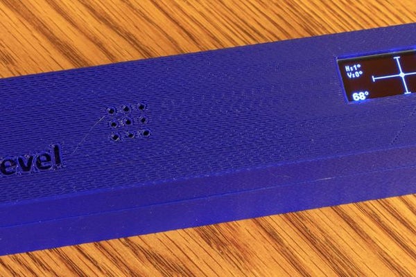
DigiLevel will provide feedback on whether a surface is level – both along the x-axis (horizontal) and y-axis (vertical). Degrees from level are shown, as well as a graphical representation on a 2 axes chart. In addition, the battery level is shown, and the current temperature in Fahrenheit or Celsius is shown (as reported by the accelerometer chip). This is minimal audible feedback – an initial tone to verify power, and then a double tone any time the level is moved from a non-level position to a level position.
I’ve provided detailed instructions on how you can make this digital level, but feel free to extend and modify on my design, much as I did on the DIY Digital Spirit Level.
Step 1: Materials
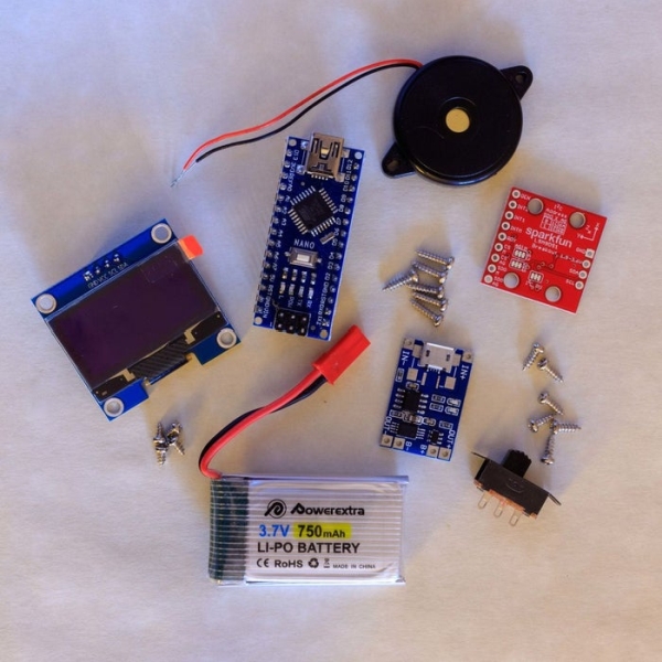
Following are the materials used in putting together this Digital Level. Most of the buying links are for multiple pieces, which are typically cheaper than buying the individual components. As an example, the TP4056 chip comes with 10 pieces for $9 (less than $1/TP4056), or it can be bought individually for $5.
- TP4056 Li-Po battery charger (Amazon – http://a.co/d/eKVM6PE)
- LSM9DS1 accelerometer (Amazon – http://a.co/d/9rqVIgh)
- Arduino Nano (Amazon – http://a.co/d/fTfFmSA)
- 128×64 OLED LCD Display (Amazon – http://a.co/d/cPbYohJ)
- Piezo speaker (Amazon – http://a.co/d/bHIjlQO)
- 3.7V Li-Po battery (Amazon – http://a.co/d/1v9n7uP)
- M2 pan head self-tapping screws – 4 M2x4, 6 M2x6, and 6 M2x8 screws are needed (eBay – https://ebay.us/elpD0A)
- Slide switch (Amazon – http://a.co/d/9JGSyHE)
With the exception of the screws, the links provided will take you to Amazon. Nearly all of these items, however, can be purchased on eBay or direct from China at a significant discount. Just keep in mind that ordering from China can result in long lead times (3-4 weeks is not unusual).
Note also that there are alternatives for many of these components. For instance, you could substitute a different accelerometer for the LSM9DS1 (such as the MPU-9205). You could replace the Arduino Nano by using any Arduino-compatible processor with the proper GPIO pins.
In particular, the LSM9DS1 is one I bought on sale at Sparkfun for less than $10, but it is normally higher priced; the MPU-9025 (http://a.co/d/g1yu2r1) provides similar functionality at a lower price.
If you make a substitution, you will likely need to modify the case (or at least how you mount the component in the case) and you will likely need to modify the software to connect to the alternative component. I do not have those modifications – you will need to research and update as appropriate.
Step 2: Wiring Diagram
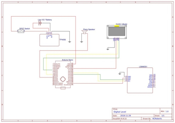
The wiring schematic details how the various electronic components are wired to each other. Red lines represent positive voltage while black lines represent ground. Yellow and green lines are used for data signals from the accelerometer and to the OLED LCD display. You’ll see how these components are wired together in the following steps.
Step 3: Make the Case
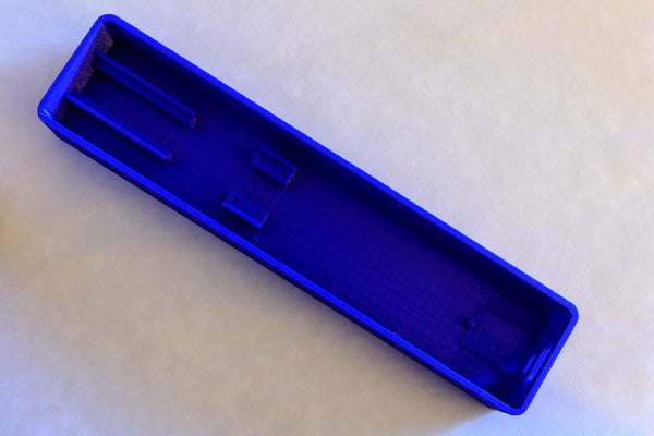
If you have a 3D printer, the case can be printed fairly easily. The STL files included in this Instructable. If you don’t have a 3D printer, you can upload the STL files to a 3D printer bureau (such as this one) and have them printed for you.
I printed mine with no brim or raft (and no supports) and 20% infill, but you can print yours however you’re used to printing. Each piece should be printed separately, laying flat. You may need to rotate it 45 degrees to get it to fit the printer bed. Mine was printed using a Monoprice Maker Select Plus with a bed size of 200 mm x 200 mm – each piece took about 12 hours to print. If you have a smaller bed, it may not fit. Scaling is not recommended as the mounts for the electronic components will then not be scaled appropriately.
Step 4: Wire the Components to a Breadboard to Verify Connectivity (optional)
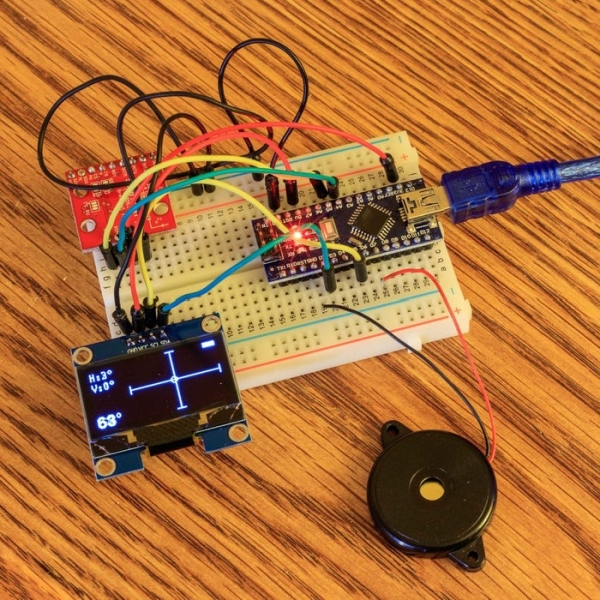
I strongly recommend wiring the primary components to a breadboard to verify connectivity before proceeding with the mounting of the components inside the case. You can download the software to the Arduino Nano (see the next step), and to verify that the OLED LCD display is correctly wired and is operational, and that the accelerometer has been correctly wired and that it is reporting its data to the Arduino Nano. Also, this can be used to verify the operation of the optional piezo speaker.
I did not connect the battery and charger to the breadboard at this stage – connecting the switch to control the battery is done after you mount the switch to the case. The last picture shows how this looks prior to wiring.
Step 5: Download the Software to the Arduino Nano
The software is loaded to the Arduino Nano using the Arduino IDE. This can be done at any time during the process of building the DigiLevel, but is best done when the components have been wired using a breadboard (see the previous step) to verify correct wiring and operation of the electrical components.
The software requires that 2 libraries be installed. The first is the U8g2 library (by oliver) – you can install this by clicking on ‘Sketch -> Include Library -> Manage Libraries…’ in the Arduino IDE. Search for U8g2 and then click on Install. The second library is the Sparkfun LSM9DS1 library. You can get instructions on how to install that library here.
After the library specifications, the software has a setup section and a main processing loop. The setup section initializes the accelerometer and the OLED LCD display, and then displays a startup screen prior to showing the main display. If a speaker is connected, it will play one beep on the speaker to signify the power on status.
The main processing loop is responsible for reading the accelerometer, obtaining the x and y angles and then displaying the values as a set of absolute numbers and also pictorially on a graph. The temperature reading from the accelerometer is also displayed (in either Fahrenheit or Celsius). If the level was previously non-level, when it returns to level it will generate two beeps on the speaker (if connected).
Finally, the voltage from the battery is obtained to determine and display the current battery level. I don’t know how accurate this code is, but it is accurate enough to show a full battery and the gradual draw down of the battery level during use.
Step 6: Mount and Wire the OLED Display and Piezo Speaker
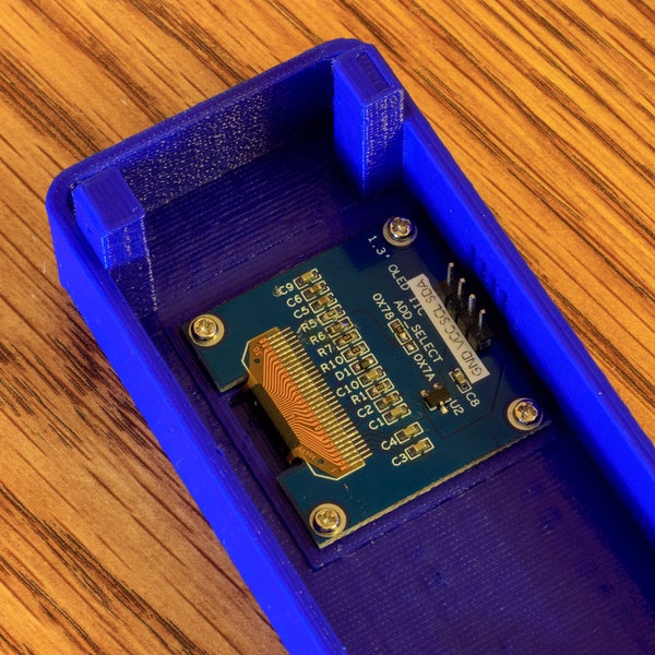
The 1.3″ OLED display (128×64) mounts to the top half of the case using 4 M2x4 pan head self-tapping screws. I suggest you connect your wires to the the display prior to mounting. This ensures that you can see how the pins are labeled as you are connecting the wires. Once the display is mounted, you won’t be able to see the labels for the pins. You’ll notice that I added a label to the back side of the display so that I could remember the pin values (since I didn’t do this the first time and I wired it incorrectly…).
The speaker is used to emit a brief tone when the Digital Level is turned on to verify that the battery is good and that it’s operational. It also emits a double tone whenever the level is moved from a non-level position to a level position. This is to provide an audible feedback as you’re positioning the level or whatever the level is on. It is mounted to the top half of the case using 2 M2x4 pan head self-tapping screws. You do not need a speaker – the DigiLevel will operate just fine without it, however you will be missing any audible feedback.
Step 7: Mount and Wire the Battery, Battery Charger, and Switch
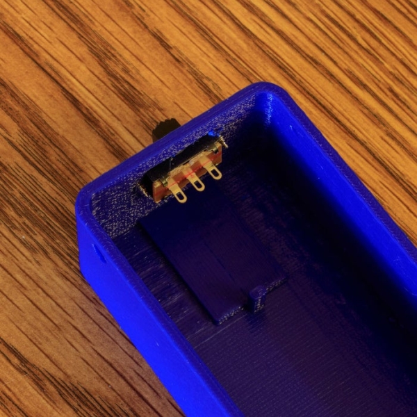
The switch needs to be mounted to the case prior to connecting it to the battery. This is because if you wire it first, you won’t be able to mount the switch without disconnecting it. So mount the switch first, then mount the pre-wired TP4056 and Li-Po battery, then complete the wiring to the switch.
The TP4056 has 4 wiring pads: B+, B-, Out+, Out-. You will want to wire the battery to the B+ (positive voltage) and B- (ground) connections. The Out- connection is used for the ground that will go to the Arduino Nano, and the Out+ is connected to one pin of the switch. The second pin of the switch is then wired to the VIN of the Arduino Nano.
My soldering job is not the best – I like to use heat-shrink tubing to cover and insulate the soldered joint. You’ll notice that on one of the soldered connections here, the heat-shrink tubing was impacted by the heat of the soldering and it shrunk before I was able to move it.
Source: DigiLevel – a Digital Level With Two Axes