Let’s get the math over right off the bat. There are a LOT of attempts to describe how Ohm’s Law works, each one nerdier than the last. Here’ one I like. Warning: SFWBN (safe for work but nerdy).
V = voltage measured in volts – the difference in electrical potential.
I = Current measured in Amps or Amperes – the rate of the flow of electrons.
R = Resistance measured in Ohms (Ω) – opposition to the flow of the current.
V = I * R
I = V / R
R = V / I
It is good to know where “power” fits in also. Power, measured in watts, is the Current (Ampes) multiplied by the Voltage. Mostly you see this equation as W = V * I
Sometimes you see this expressed as a confusing looking wheel. (coincidentally also the coolest tattoo ever)
Oh, and sometimes Volts are expressed with and E instead of a V. They do this because they hate you.
Example: a typical 100 Watt bulb – how many amps does it use? 100 watts / 120 volts = .83 amps
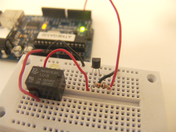
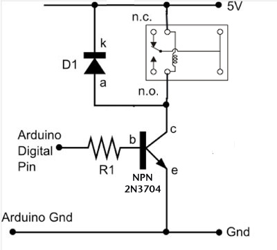
Relays are a great way to separate your low voltage Arduino circuit from a much higher voltage circuits to run motors or lights. Relays are all over – cars, computers they are an electronics staple. Each kind will be wired differently and be able to handle different voltages. we have two different kinds (the black cube ones are more reliable) – they work about the same once you’ve determined the inputs.
This circuit uses a transistor – there are two families of transistor this size, NPN or PNP. You can often swap out different ones from the same family and the circuit will still work fine, but you can’t swap out a PNP for an NPN. Of course they look exactly the same so you have to use the i-tubes to figure out which is which. enjoy.
The diagram does not include the motor circuit. You should be able to hear the actual relay switch turn on and off, but the real test it having it turn on a motor. The photograph does include the diode which helps keep the electricity flowing in the right direction and the relay working consistently. Diodes have a a correct orientation – in this case the white line on the diode goes towards the +5volt.
Simple code for the relay. Requires the Arduino loaded with Firmata.
	import processing.serial.*;
	import cc.arduino.*;
	Arduino arduino;
	int transistorPin = 5;

	void setup()
	{
	  size(255, 255);
	  arduino = new Arduino(this, Arduino.list()[0], 57600);
	  arduino.pinMode(transistorPin, Arduino.OUTPUT);
	}
	void draw()
	{
	  if ( mousePressed == true) {
	    arduino.digitalWrite(transistorPin, Arduino.HIGH);
	  }
	  else {
	    arduino.digitalWrite(transistorPin, Arduino.LOW);
	  }
	}
There’s a small deviation from the diagram – the wire going into pin 4 should go in a PWM port for the analog example to work right – the examples below have it on pin 5.
With an H-Bridge (or in our case with a Dual H Bridge) you can control a DC motor’s sped and direction. This is awesome. In the diagram below the motor is running off a battery. You can use an external wall wart power supply if you want instead.
For more detail: DC motors Relays Usung Arduino