Summary of Arduino controlled Rotary Stewart Platform
This article details the construction of an Arduino-controlled Rotary Stewart Platform capable of six degrees of freedom motion, specifically designed to hold DSLR cameras. Using hobby servos instead of linear actuators, the platform achieves precise positioning with a 2kg load capacity and low power consumption. The build involves cutting acrylic parts, assembling connecting rods, and programming the Arduino for servo control.
Parts used in the Rotary Stewart Platform:
- Hobbyist servos
- Arduino Uno board
- IRDA sensor
- LCD with I2C interface
- 4mm acrylic sheets
- Connecting rods (approx. 12cm)
- Screws
- Rubber or foam pad
- Double sided tape
- Caul glue (CA glue)
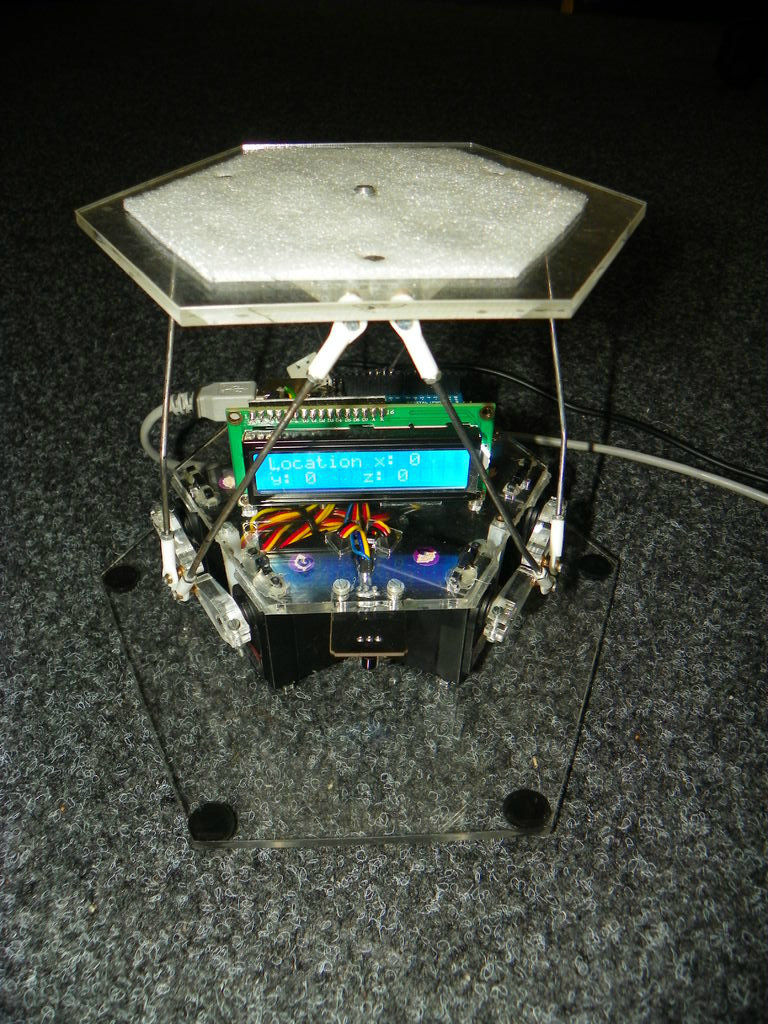
This instructable is about building a Rotary Stewart Platform. It allows to position its moving platform in six degrees of freedom. This specific platform is designed to be able to position a DSLR or any other digital camera.
This version of Stewart Platform uses instead of linear actuators just ordinary hobbyist servos for motion. Whole platform is controlled by an Arduino Uno, it computes all necessary equations to get the platform into right position and also controls servos.
Video of movement of completed platform can be seen here. Quality is not very good, but camera with better picture was at the time of capture on the platform. It was set-up for random position every 4 seconds.
Some informations about platform:
- weight of load can be up to 2Kg (platform tested with 1.5Kg with no observable problems during moves in whole range of movements), theoretically platform should be able to cope with even higher loads, but it wasn’t tested with such load
- low power consumption – with load of 1kg was consumption of around 5W.
- very good fineness of moves – smallest possible move is around 1mm
- perfect ability to repeatedly achieve the same positions.
- good stability of platform even with big loads.
All source files for platform (templates, Arduino source code, code for communication library can be found here.
Price of platform mostly depends on the price of servos and of the Arduino board. Cutting of parts, all other needed parts cost at most 50$. Total price can be around 150$.
IrDA and LCD with I2C interface were bought from ebay, they are very cheap (together around 10$)
Parts of platform are cutted from acrylic, i used 4mm acrylic.
Needed tools:
- drill
- screwdriver
- tools needed for soldering and creation of PCB for connecting external power supply
- measuring tools
- double sided tape
In case of any questions, feel free to contact me.
Step 1: Building moving platform
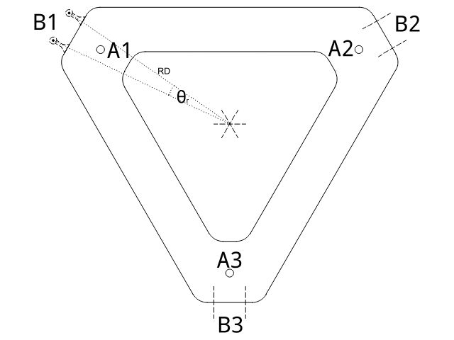
We start by cutting parts from acrylic, here we will use templates from files platform_bot and platform_top. This platform is divided into two parts for better universality, just by changing top part of platform you can adapt it for various purposes. They are put together using screws placed in holes A1-A3.
Dimensions are chosen with respect to size of ordinary DSLR. Platform can be changed to be smaller or bigger.
At denoted places B1-B3 in bottom part of platform it is needed to drill holes which are used for anchoring of connecting rods. On third picture you can see proper way of doing that. These weird deformations in acrylic were caused by using CA glue to fix screws in acrylic.
On top of the moving platform it is necessary to place a piece of rubber or foam and fix it there with double sided tape. It will prevent unwanted rotations and movements of camera on the platform.
Length of connecting rods should be around 12cm and they should be bended as can be seen on picture of completed platform. This bend greatly improves range of movements. Length of rods should be chosen so that the angle between servo arms in horizontal position and the rod is around 70°.
For more detail: Arduino controlled Rotary Stewart Platform
- What is the primary function of this project?
The project builds a Rotary Stewart Platform that positions a moving platform in six degrees of freedom. - Can this platform hold a DSLR camera?
Yes, the platform is specifically designed to position a DSLR or any other digital camera. - What type of actuators are used for motion?
This version uses ordinary hobbyist servos instead of linear actuators. - How much weight can the platform support?
The weight of the load can be up to 2Kg, and it was tested with 1.5Kg without issues. - What material is used to cut the parts?
All parts of the platform are cut from 4mm acrylic. - What is the smallest possible move size?
The platform offers very good fineness of moves with a smallest possible move around 1mm. - Does the platform consume a lot of power?
No, it has low power consumption, using around 5W with a load of 1kg. - What tools are needed for soldering?
You need tools for soldering and creating a PCB for connecting the external power supply.