
Summary of D-Led Shield v1.0 (for monitoring)
This article presents a DIY LED shield for Arduino designed to monitor I/O pin states (HIGH/LOW) during prototyping. The project involves soldering 19 LEDs in series with resistors onto a PCB, connected via header pins to the Arduino board. It offers a cost-effective alternative to commercial shields, particularly useful where specialized components are scarce.
Parts used in the D-Led Shield:
- Soldering gun
- Resistors (270 ohms)
- 5mm Green square LED
- Soldering lead
- Header pins or long pins
- Arduino MCU
- PCB
- Tact switch (2 pins)
Good day fellow enthusiast!
Here is one of my latest and simplest shield designs for an arduino board.
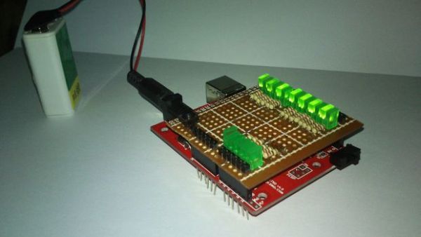
The thing here is, sometimes we have a hard time checking out which I/O pins are LOW or HIGH, especially when we are dealing with LED, motors, etc. Now, here is one of the solutions that you can make in order to have yourself a smooth sailing progress in programming your prototype or project.
One of the shields we sell at our shop in e-Gizmo Mechatronix Central, is an LED shield. It is one of the shields that can help you monitor your I/O pins. Another thing is, in some countries, this kind of shield is not sold and most probably, only prototyping shields are available.
I shall now provide you a DIY LED shield that will you a LOT in your projects.
Features:
19 LED in series with your arduino’s I/O pins for monitoring.
Step 1: Materials
Soldering gun,
Resistors (270 ohms),
5mm Green square LED,
Soldering lead,
Header pins or long pins,
Arduino MCU,
PCB,
Tact switch (2 pins)
Cost analysis:
(in Philippine Peso)
LED P2.50 x 19 = P47.50
Resistors (depends on the LED you used) P0.25 x 19 = P4.75
PCB (smallest size) = P10.00
Tact switch = P2.50
1×40 Header pins = P14.00
(OPTIONAL: x2 6 Long pins & x2 8 Long pins) = P48.00
Total = P78.75 (relatively cheap right?)
NOTE: The long pins are optional since you can also make a shield using header pins alone however, you cannot mount another shield on your shield if you did it the way I did it.
Step 2: Schematic
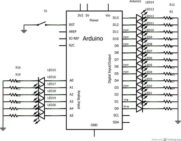
Here is how I soldered the shield and I know, I’m actually not proud of how I solder stuff since my soldering gun is not really that great.
The running “rail-like” solders are all connected to the ground.
Step 3: Procedures
STEP 1: Buy the materials! I am very particular with this since in some countries, hunting the materials are really tough. So I’m going to give you tips wherever you are in this universe.
In North America, check out Radioshack or try buying from Sparkfun through shipping.
In the Philippines, you can visit Raon and look for DEECO. They sell LEDs for a very low price wherein you can buy 20pcs for I think P25.00 only.
If you have the chance, visit our shop (e-Gizmo) in Taft. The prices of the materials are listed above and I made our shop as a reference for the materials’ prices.
http://www.e-gizmo.com
For more detail: D-Led Shield v1.0 (for monitoring)
- What is the primary purpose of this DIY shield?
To monitor which I/O pins are LOW or HIGH when dealing with LEDs and motors. - How many LEDs are included in the design?
The shield features 19 LEDs connected in series with the Arduino's I/O pins. - What resistor value is required for the LEDs?
The project specifies using 270 ohm resistors for each LED. - Can I use only header pins without long pins?
Yes, but you cannot mount another shield on top if you do not use the long pins. - Where can I buy materials in North America?
You can check out Radioshack or try buying from Sparkfun through shipping. - Is there a specific shop mentioned for low-priced LEDs in the Philippines?
Raon and DEECO are recommended for purchasing LEDs at very low prices. - What is the total estimated cost in Philippine Peso?
The total cost listed for all materials is P78.75. - Which color and type of LEDs are specified?
The project requires 5mm Green square LEDs.
