Summary of Cyber Tail
This article guides readers in building a cybernetic tail using accessible technologies like Arduino and 3D printing. The project, part of a university seminar, allows users to create a tail that reacts to hand gestures via an accelerometer and eye blinks detected by an IR sensor. By combining electronic components with foam structures, the author demonstrates how digital fabrication can extend human movement into the physical world for interactive expression.
Parts used in the Cyber Tail:
- Arduino Uno
- Infrared reflective sensor module TRCT5000
- Accelerometer MPU6050
- Servo motor SG90 (x4)
- Capacitor (x4)
- 9v battery
- EPE foam rods
- Breadboard
- Jumping wires
- USB cable
- Eye glasses or goggles
- Strings
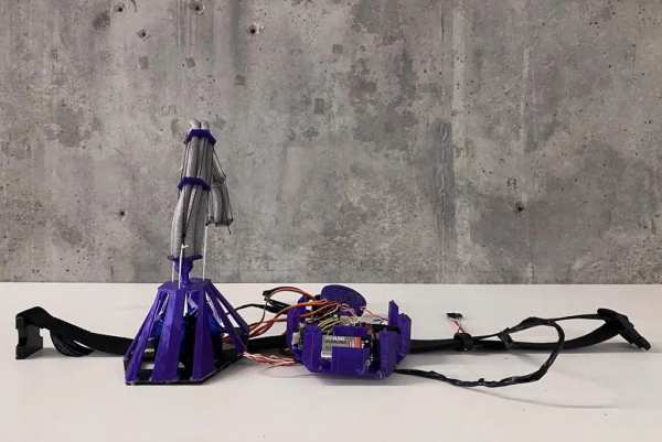
About 25 million years ago, our ancestors lost their tails during the evolution to better adapt to the the environment. Today, as we live in the digital age, our bodies are evolving along with the cyber world. What would a cybernetic tail bring to our daily life? With the easily accessible technologies, such as Arduino and 3D printing, you can make your own cyber tail!
// This project was undertaken as part of the Computational Design and Digital Fabrication seminar in the ITECH masters program at the University of Stuttgart.
Supplies
- Arduino Uno
- Infrared reflective sensor module TRCT5000
- Accelerometer MPU6050
- Servo motor SG90 (x4)
- Capacitor (x4)
- 9v battery
- EPE foam rods
Step 1: Making the Base Frame
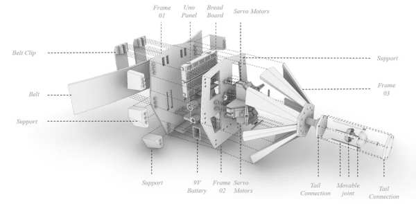
The base frame can hold all the necessary electronic parts. You can either download the attached 3d model and print it on a 3d printer, or just be creative and make it using foam boards, cardboards, or wood boards. As long as it is strong enough to hold all the parts and a 1 kg tail shown in the exploded diagram.
Step 2: Attaching Electronic Parts to the Frame
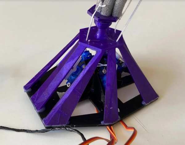
Attached Arduino Uno, breadboard, 9v battery, and 4 mini servo motors to the frame as indicated in the assembly diagram in step 1.
Step 3: Connecting the Circuit
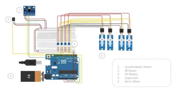
Follow the diagram and connect the circuit using jumping wires. Two longer wires (about 0.6 – 1m long) will be needed for extending the sensors.
Step 4: Coding
Connect Arduino Uno with computer using a USB cable and upload the cade below.
In order to use the accelerometer to get the hand position, the MPU6050 library will need to be installed on the Arduino IDE. Go to this webpage https://www.arduino.cc/reference/en/libraries/mpu6050/ and download the latest version. Then open the Library Manager in the Arduino IDE and install it from there.
int IRSensor = 10; // connect IR sensor module to Arduino pin D10
int LED = 13; // connect LED to Arduino pin 13

#include <Servo.h>
#include <Wire.h>
#include <MPU6050.h>

MPU6050 mpu;

Servo servo1;
Servo servo2;
Servo servo3;
Servo servo4;

int pos1 = 90;
int pos2 = 90;
int pos3 = 90;
int pos4 = 90;


void setup()
{
//Acceleration sensor

  Serial.begin(115200);
  Serial.println("Initialize MPU6050");

  while(!mpu.begin(MPU6050_SCALE_2000DPS, MPU6050_RANGE_2G))
  {
    Serial.println("Could not find a valid MPU6050 sensor, check wiring!");
    delay(500);
  }


  // If you want, you can set accelerometer offsets
  // mpu.setAccelOffsetX();
  // mpu.setAccelOffsetY();
  // mpu.setAccelOffsetZ();

  checkSettings();

  Serial.println("Serial Working"); // Test to check if serial is working or not
  pinMode(IRSensor, INPUT); // IR Sensor pin INPUT

  servo1.attach(3); //servo1 signal connected to pin3
  servo2.attach(5); //servo2 signal connected to pin5
  servo3.attach(6); //servo3 signal connected to pin6
  servo4.attach(9); //servo4 signal connected to pin9
}


void checkSettings()
{
  Serial.println();
  Serial.print(" * Sleep Mode:            ");
  Serial.println(mpu.getSleepEnabled() ? "Enabled" : "Disabled");
  Serial.print(" * Clock Source:          ");
  switch(mpu.getClockSource())
  {
    case MPU6050_CLOCK_KEEP_RESET:     Serial.println("Stops the clock and keeps the timing generator in reset"); break;
    case MPU6050_CLOCK_EXTERNAL_19MHZ: Serial.println("PLL with external 19.2MHz reference"); break;
    case MPU6050_CLOCK_EXTERNAL_32KHZ: Serial.println("PLL with external 32.768kHz reference"); break;
    case MPU6050_CLOCK_PLL_ZGYRO:      Serial.println("PLL with Z axis gyroscope reference"); break;
    case MPU6050_CLOCK_PLL_YGYRO:      Serial.println("PLL with Y axis gyroscope reference"); break;
    case MPU6050_CLOCK_PLL_XGYRO:      Serial.println("PLL with X axis gyroscope reference"); break;
    case MPU6050_CLOCK_INTERNAL_8MHZ:  Serial.println("Internal 8MHz oscillator"); break;
  }

  Serial.print(" * Accelerometer:         ");
  switch(mpu.getRange())
  {
    case MPU6050_RANGE_16G:            Serial.println("+/- 16 g"); break;
    case MPU6050_RANGE_8G:             Serial.println("+/- 8 g"); break;
    case MPU6050_RANGE_4G:             Serial.println("+/- 4 g"); break;
    case MPU6050_RANGE_2G:             Serial.println("+/- 2 g"); break;
  }

  Serial.print(" * Accelerometer offsets: ");
  Serial.print(mpu.getAccelOffsetX());
  Serial.print(" / ");
  Serial.print(mpu.getAccelOffsetY());
  Serial.print(" / ");
  Serial.println(mpu.getAccelOffsetZ());

  Serial.println();
}

void loop(){
  //IR sensor read
  int sensorStatus = digitalRead(IRSensor); // Set the GPIO as Input

  //Accel Sensor read
  Vector rawAccel = mpu.readRawAccel();
  Vector normAccel = mpu.readNormalizeAccel();

  Serial.print(" Xraw = ");
  Serial.print(rawAccel.XAxis);
  Serial.print(" Yraw = ");
  Serial.print(rawAccel.YAxis);
  Serial.print(" Zraw = ");

  Serial.println(rawAccel.ZAxis);
  Serial.print(" Xnorm = ");
  Serial.print(normAccel.XAxis);
  Serial.print(" Ynorm = ");
  Serial.print(normAccel.YAxis);
  Serial.print(" Znorm = ");
  Serial.println(normAccel.ZAxis);

  // IR sensor
  if (sensorStatus == 1) // Check if the pin high or not
  {
    // if the pin is high turn off the onboard Led
    digitalWrite(LED, LOW); // LED LOW
    Serial.println("Motion Detected!"); // print Motion Detected! on the serial monitor window

   servo1.write(180);
   delay(20);
   servo3.write(0);
   delay(20);

  }

  if  (sensorStatus == 0)
  {
    //else turn on the onboard LED
    digitalWrite(LED, HIGH); // LED High
    Serial.println("Motion Ended!"); // print Motion Ended! on the serial monitor window
   servo1.write(0);
   delay(20);
   servo3.write(180);
   delay(20);
  }


  if (normAccel.YAxis >= 0)
  {
  pos2 = round(normAccel.YAxis * 18);
  }
  else {
    pos4 = round(normAccel.YAxis * -18);
  }
  servo2.write(pos2);
  delay(20);
  servo4.write(pos4);
  delay(100);

}
Step 5: Making the Eye Blinking Sensor
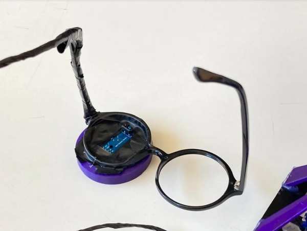
Attached the IR reflective sensor module TRCT5000 to a pair of eye glasses or goggles. Adjust the tiny potentiometer on the sensor module until it can properly recognize your eye blinking.
Step 6: Making the Tail
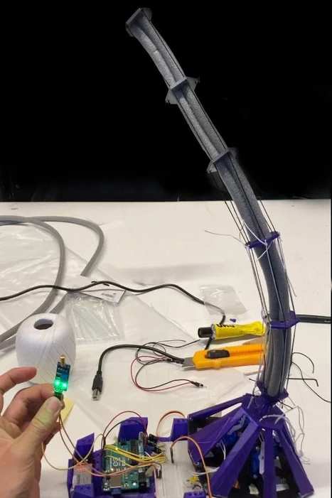
Cut the EPE foam tubes into 10cm segments and glue them onto the 3d printed “tail bones”. Run 4 strings through the tail bones and connect the strings to the arms of the 4 servo motors. Adjust the tightness of the strings until the tail is in desired shape.
Step 7: Wear It!
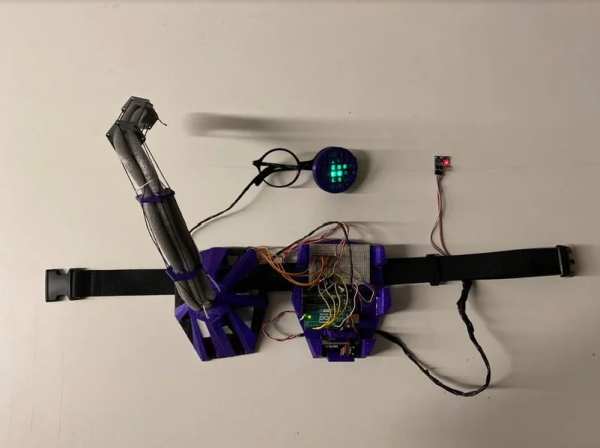
Now the Cyber Tail is ready for wearing! Put it on your belt and wear the blinking sensor. Tape the Accelerometer to you hand. The tail will dance along with you unconscious eye blinking and hand gestures.
Source: Cyber Tail
- What technology is required to make this cyber tail?
The project uses easily accessible technologies such as Arduino and 3D printing. - How does the tail detect eye blinking?
An Infrared reflective sensor module TRCT5000 attached to glasses or goggles recognizes the blink. - Can I build the base frame without a 3D printer?
Yes, you can use creative materials like foam boards, cardboards, or wood boards if they are strong enough. - Which library must be installed on the Arduino IDE?
You need to install the MPU6050 library to use the accelerometer for hand position detection. - How many servo motors are needed for the tail?
The project requires four mini servo motors, specifically the SG90 model. - What material is used to construct the tail segments?
EPE foam tubes are cut into 10cm segments and glued onto 3D printed tail bones. - Where should the Accelerometer be placed?
The Accelerometer should be taped to your hand to control the tail's movement. - How are the strings connected to the tail mechanism?
Four strings run through the tail bones and connect to the arms of the four servo motors.