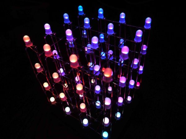
Summary of 4x4x4 RGB LED Cube using Arduino
The author shares a guide for building a 4x4x4 RGB LED cube using an Arduino-compatible Atmega328 microcontroller. The project emphasizes learning electronics through hands-on assembly, starting with basic components and expanding to advanced features like audio responsiveness and custom animations. The build process involves creating a precise grid for LED placement, soldering layers, and programming the cube with specific software libraries.
Parts used in the 4x4x4 RGB LED Cube:
- 1x Atmega328 (With arduino Optiboot bootloader)
- 3x TLC5940
- 4x P-Channel MOSFETs
- 3x 4K7 Resistors
- 3x 16 pin Male and Female headers
- 1x 4 pin Male and female header
- 1x 28pin IC socket
- 1x 1000uf 10v capacitor
- 1x 0.1 uf ceramic capacitor
- 2x 22pf capacitors
- 1x 16Mhz crystal oscillator
- 64x RGB common ANODE LEDs
- Solder
- 3x 8k2 resistors (optional low power mode)
- 3x 3pin male headers (jumper selection)
- 3x jumpers (power usage/brightness setting)
- 2+x 64KB EEPROMs (custom animations)
- 1x DIP switch (mode selection)
- 2x MSGEQ7 chips (audio analyzing)
- Black paint
A while ago, when I first started using Arduino, my first project was a 4x4x4 LED cube, I built it from a Guide I found here in Instructables, I didn’t know anything about programming, and little about electronics, yet I was able to build it and make it work, I didn’t know how it worked but it did!
That success made me like this page a lot and also made me want to make guides like that one, well documented and properly explained, enabling people to make cool things, at first without them knowing how they work, and from there, from a working piece, start learning and understanding how it works.
Step 1: Materials
For the most basic cube you will need;
- 1x Atmega328 (With arduino Optiboot bootloader)
- 3x TLC5940
- 4x P-Channel MOSFETs
- 3x 4K7 Resistors
- 3x 16 pin Male and Female headers
- 1x 4 pin Male and female header
- 1x 28pin IC socket
- 1x 1000uf 10v capacitor
- 1x 0.1 uf ceramic capacitor
- 2x 22pf capacitors
- 1x 16Mhz crystal oscillator
- 64x RGB common ANODE LEDs (it is very important that you check your LEDs are common ANODE, or else, the cube won’t work!!)
- a LOT of Solder!
for more advanced functions;
- 3x 8k2 resistors for optional, low power mode.
- 3x 3pin male headers for jumper selection of the power mode
- 3x jumpers for selecting the power usage/brightness setting
- 2+x 64KB EEPROMs for storing custom animations
- 1x DIP switch for selecting different modes (random, serial, music responsive, random2, custom animations, etc.)
- 2x MSGEQ7 chips for audio analyzing and music response.
- Black paint
Tools;
- An Arduino to use as a USB to Serial converter for programming
- An USBTinyISP if your Atmega chip is not pre-Bootloaded
- A Multimeter for troubleshooting and checking connections
- Some way of cutting PCBs, I used a Circular Saw, but you can use whatever you have in hand.
- Diagonal cutters
- A Sharpie or any kind of marker
- A Drill/Drillpress
- A Cutter or Xacto knife
Step 2: Planning
First you’ll need to decide the size of your cube, it can be any size you want to, but nothing bigger than what the leads on the LEDs allow, my LEDs had 28mm leads, so I decided my spacing was going to be 25mm between LEDs. THis is usually a good size.
Step 3: Make a grid
To be able to make all the layers with the same spacing and keed all the LEDs “Snapped to Grid” we need to actually make a grid, for this we will need;
a piece of scrap wood bigger than the size of your cube
a Bit of the right size for your LEDs, its better to measure it with a caliper, but if you don’t have one, just trust your maths and the LED Manufacturer’s specifications.
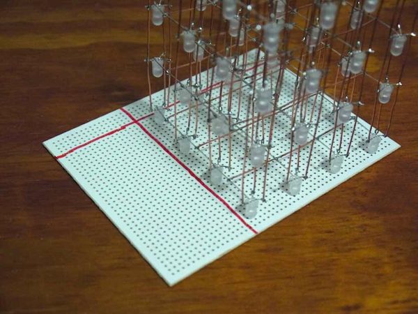
my drill press has a table with 2 axis control, it has handles and moves 1mm per revolution, so I just counted 10 turns between each hole, make sure to make your holes at 0 on both Axis (x and Y). Also make sure to set the stopper for the Z axis or you will drill all the way thru your drill press.
I made my grid bigger, 5×5 in case I, in the future want to build another bigger (or smaller) LED cube.
- 1x Atmega328 (With arduino Optiboot bootloader)
- 3x TLC5940
- 4x P-Channel MOSFETs
- 3x 4K7 Resistors
- 3x 16 pin Male and Female headers
- 1x 4 pin Male and female header
- 1x 28pin IC socket
- 1x 1000uf 10v capacitor
- 1x 0.1 uf ceramic capacitor
- 2x 22pf capacitors
- 1x 16Mhz crystal oscillator
- 64x RGB common ANODE LEDs (it is very important that you check your LEDs are common ANODE, or else, the cube won’t work!!)
- a LOT of Solder!
For more detail: 4x4x4 RGB LED Cube using Arduino
- What type of LEDs are required for this cube?
You must use RGB common ANODE LEDs, otherwise the cube will not work. - How do you determine the spacing between LEDs?
Spacing is usually around 25mm if your LED leads are 28mm long, ensuring they fit without exceeding lead length limits. - Can I change the size of the LED cube?
Yes, you can decide any size you want, but it cannot be bigger than what the LED leads allow. - What tools are needed to cut the PCBs?
You need a way to cut PCBs such as a circular saw, diagonal cutters, or whatever tool you have in hand. - How can I select different operating modes on the cube?
A DIP switch is used to select modes like random, serial, music responsive, random2, and custom animations. - Which chip is used for audio analyzing and music response?
The MSGEQ7 chip is used for audio analyzing and enabling music response features. - What is the best way to ensure all LEDs are aligned on a grid?
Build a grid using scrap wood and a drill press with axis control to keep LEDs snapped to the grid. - How do I store custom animations on the device?
Use 2 or more 64KB EEPROMs to store custom animations for the cube.