Summary of Cwik Clock v1.0 – An Arduino Binary Clock
This article guides users in building a custom Arduino binary clock that displays hours and minutes via LEDs, seconds on an analog meter, and includes time-setting knobs. It covers circuit design, programming logic to handle millis() rollovers, and assembly of both a prototype using an Uno board and a final custom PCB version.
Parts used in the Cwik Clock:
- Arduino Uno
- ATmega328P-PU microcontroller
- 14 LEDs (2Vf @ 20mA)
- Resistors (220 Ohm, 150 Ohm, 10K Ohm, 100K Ohm)
- Potentiometers (2x, preferably linear)
- SPDT switch
- Momentary normally open button/switch
- Analog ammeter/meter (50 uA)
- 7805 voltage regulator (5V)
- Capacitors (10 uF x2, 22 pF x2)
- 16 MHz clock crystal
- Project box
- Wire (22 AWG)
- 9V power supply with female jack
- Perf board
- LED mounting clips
- 28-pin socket
- Knobs for potentiometers
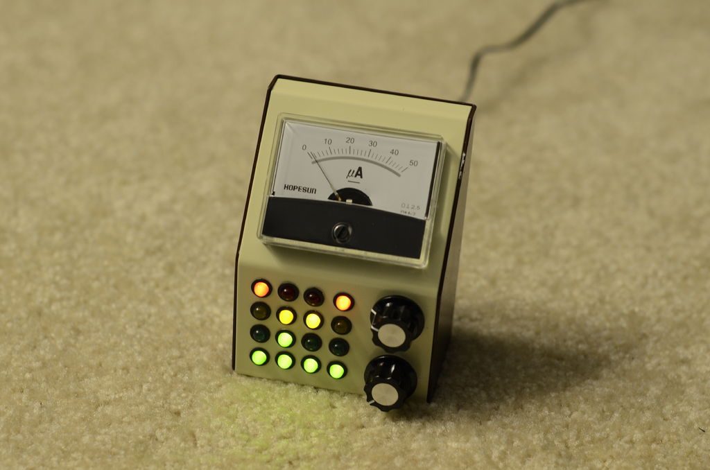
This is a guide to building an Arduino-powered clock that uses LEDs to display a 24-hour clock (hours and minutes) as binary digits, an analog meter to display the seconds, a switch to toggle between time-display and time-setting mode, and 2 knobs for setting the hours and minutes. This was designed from scratch, but is an improvement over other Arduino binary clocks that miss milliseconds here and there. This clock is extremely accurate and can be used and trusted.
To clear things up right away, Cwik is my last name and it’s pronounced “Swick”. So no, it’s not the Quick Clock, and no, it does not run quick.
We’ll start by using the Arduino Uno for prototyping, then build our own Arduino circuit from scratch for the final product. While creating out own circuit from scratch at the end is completely optional, it will allow you to continue to use your Cwik Clock, while freeing up the Uno for your next project.
Goals
There are 3 main goals for this project:
1) Familiarizing yourself with basic circuitry components – My Dad inspired me to get into electronics and circuits. After fixing some old oscilloscope by determining a resistor had blown, I was amazed that he could actually fix something (rather than throw it out and replace it). I have very little experience with circuits, but am determined to be able to hold a conversation with my dad that involves more than batteries, buzzers and light bulbs. By the end of this guide, you should gain knowledge of LEDs (safely powering them, and controlling using the Arduino), understand potentiometers (what they are, and reading their values from the arduino board), how an analog ammeter works, and using Ohm’s Law.
2) Striving for functional perfection – Go big or go home. We’re building this to high standards, a clock you can actually use and trust.
3) Making this look damn good – Although most of the concepts are simple, it doesn’t mean our product has to look it too. Some key themes in its appearance are compactness, retro styling, throwbacks to audio equipment, fit & finish, and feel. My Dad had a lot of electronic equipement laying around the basement, so some colors and elements are inspired by my vague memories. Using an analog meter on a digital clock and a potentiometer to set digital time seems backwards, but it’s what builds the charm of the Cwik Clock and differentiates itself from the countless binary clocks on the market already.
Audience
This guide is ideal for anyone looking for their 1st start-to-finish Arduino project. Elementary knowledge of the arduino platform, circuitry, and programming would be helpful, but aren’t absolutely essential.
Step 1: Materials Needed
The Arduino Uno Based Circuit (used for the majority of the steps):
-1 x Arduino Uno
-14 x LEDs, 2Vf @ 20mA
-14 x 220 Ohm resistors
-2 x potentiometers (preferrably linear and can really be any resistance, but 10K or 100K Ohm will do well)
-1 x SPDT switch
-1 x 50 uA analog meter/ammeter
-1 x 100K Ohm resistor
The Final Circuit (re-uses everything from the above list, but now we’re making an Arduino board rather than using the Uno):
-1 x ATmega328P-PU (or pull the one off of your Uno, but you’ll want to replace it with this)
-1 x project box, paint if desired
-wire (I used 22 AWG wire)
-1 x 7805 voltage regulator (5V)
-1 x 10K Ohm resistor
-2 x 10 uF capacitor
-2 x 22 pF capacitor
-1 x 16 MHz clock crystal
-1 x momentary normally open (“off”) button/switch
-2 x knobs, which fit on the potentiometers
-1 x 9V power supply
-1 x female jack for power supply
-perf board
-2 x LED (optional, these are completely unused, but form a 4×4 grid of LEDs along with 13 time LEDs, and the 1 time-setting mode LED)
-14 x LED mounting clip (or 16 if you use the 2 dummy LEDs mentioned directly above, but these mounting clips are completely optional)
-1 x 28-pin socket for mounting the microcontroller (optional, but highly recommended if you plan to adjust for error in the final step)
Step 2: Reading the Clock
In order to read the clock, the rows (starting from the bottom up) represent the numbers 1, 2, 4, and 8. To read the column, simply add the values that are lit up for the column.
Step 3: Powering the LEDs
The digital pins on the Arduino Uno output 5V DC. I purchased 2Vf @ 20mA LEDs, so the following calculations pertain to these values. Let’s calculate what type of resistors will be needed in series to power our LEDs using Ohm’s Law.
V = IR
R = V / I
R = ([voltage supplied by Arduino] – [voltage drop across LED]) / 20 mA
R = (5V – 2V) / 0.02 A
R = 150 Ω
This means the resistor should be 150Ω. However, it’s fairly common to use 220Ω resistors, and some people use even higher. The higher the resistance, the lower the intensity of the LED, but the higher the power saving (but at some point, the resistance it too high and there’s not enough voltage to power the LED). Hence, to power a single LED, we need to hook it up in series with a 150Ω resistor (or 220 to be safe), apply 5V to the anode, and attach its cathode to ground.
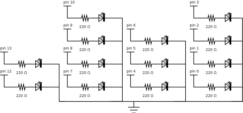
In the diagram you can see the Arduino Uno powering a single LED. No program needs to be loaded on the board since we’re just connecting directly to the 5V pin.
In order to make the clock’s display, we’ll require 13 LEDs (as shown in the previous step), each connected to their own 220Ω resistor. Rather than power the LEDs from the 5V pin, we’ll be hooking them up to the digital pins of the Uno in the next step (so that we can turn them on and off when we want).
Step 4: Programming the Clock
Program Structure
Arduino programs have 2 main methods; a method that is run once at the beginning where initialization is done (called setup), and another method which is called continuously (called loop).
In setup(), we’ll set the time to 00:00, and set up which pins are going to drive the 13 LEDs.
In loop() we’ll see if more than a second has ellapsed (and if so, increment the time), then display the time by powering the proper LEDs. The millis() method is instrumental to keeping time. It returns the number of milliseconds that have ellapsed since the circuit was powered as an unsigned long. “Unsigned” means that it will not be negative, and long refers to how many bits (32 to be exact) are used to keep track of this number (bits are the number of binary digits).
The Quirk with millis()
Since there is a finite number of bits in an unsigned long, at some point we’re going run out of digits! According to the Arduino documentation on millis(), it will wrap around (ie, reset back to zero) after approximately 50 days. How annoying would that be to have to reset your clock every 50 days? As one of the goals states, we’re striving for functional perfection and this distruptive behavior is unnacceptable. Thus, the logic in our tick() method is used to see when we wrap around and continue without anyone being the wiser.
Pin Assignments
Before we jump right in and start assigning digital pins, we’ll required a PWM (pulse width modulated) pin to display the seconds on the analog meter in a later step. On the Arduino Uno, pins 3, 5, 6, 9, 10, and 11 are enabled for PWM (as signified by the “~”). Thus, I’m saving pin 11 for the analog display, and using pins 0 – 10, 12 & 13 for the binary LED display.
The code
/*
Cwik Clock v1.0 – Prototyping the Display
Author: Dennis Cwik
Date: July 23, 2012
This program is the controller for a binary clock, with LEDs
attached to digital pins 0 through 10, 12, and 13.
This example code is in the public domain.
*/
// This can be modified for debug purposes to make a minute go by quicker.
int ONE_SECOND = 1000; // measured in milliseconds
int DELAY_BETWEEN_LOOP_CALLS = 200; // measured in milliseconds
// I didn’t come up with this, it’s from the arduino documentation
unsigned long MAX_UNSIGNED_LONG = 4294967295; // = (2 ^ 32) – 1
// 1st column of LEDs
int PIN_MIN1 = 0;
int PIN_MIN2 = 1;
int PIN_MIN4 = 2;
int PIN_MIN8 = 3;
// 2nd column of LEDs
int PIN_MIN10 = 4;
int PIN_MIN20 = 5;
int PIN_MIN40 = 6;
// 3rd column of LEDs
int PIN_HOUR1 = 7;
int PIN_HOUR2 = 8;
int PIN_HOUR4 = 9;
int PIN_HOUR8 = 10;
// 4th column of LEDs
int PIN_HOUR10 = 12;
int PIN_HOUR20 = 13;
// the last time the seconds in the time were incremented
unsigned long m_lastTick;
// used to tell us if we’re setting the time or not
boolean m_inTimeSetMode = false;
// the time
byte m_second;
byte m_minute;
byte m_hour;
// the setup routine runs once when you press reset
void setup()
{
// initialize the pins used for outputting time as OUTPUT
pinMode(PIN_MIN1, OUTPUT);
pinMode(PIN_MIN2, OUTPUT);
pinMode(PIN_MIN4, OUTPUT);
pinMode(PIN_MIN8, OUTPUT);
pinMode(PIN_MIN10, OUTPUT);
pinMode(PIN_MIN20, OUTPUT);
pinMode(PIN_MIN40, OUTPUT);
pinMode(PIN_HOUR1, OUTPUT);
pinMode(PIN_HOUR2, OUTPUT);
pinMode(PIN_HOUR4, OUTPUT);
pinMode(PIN_HOUR8, OUTPUT);
pinMode(PIN_HOUR10, OUTPUT);
pinMode(PIN_HOUR20, OUTPUT);
// initialize clock variables
m_lastTick = 0;
setTime(0, 0, 0);
}
// the loop routine runs over and over again forever
void loop()
{
// see if we’re setting the time, or letting time flow normally
if (m_inTimeSetMode)
{
getTimeFromPots();
}
else
{
tick();
}
// now that the time has been updated, show the time
displaySeconds();
displayMinutes();
displayHours();
// arbitrary delay so that we’re not processing away 100% of the time,
// an act of power saving
delay(DELAY_BETWEEN_LOOP_CALLS);
}
/**
* A helper method to set m_second, m_minute, and m_hour.
*/
void setTime(byte newHour, byte newMinute, byte newSecond)
{
m_second = newSecond;
m_minute = newMinute;
m_hour = newHour;
}
/**
* This method keeps track of the logical flow of time. If enough time has
* passed since the last time it was called, m_second, m_minute, and m_hour
* will be updated appropriate. This takes into account that millis() rolls
* over roughly every 50 days.
*/
void tick()
{
unsigned long now = millis();
unsigned long msElapsed;
// first we need to find out how much time has passed since the last time we
// called tick()
if (now < m_lastTick)
{
// gasp, either we’ve succeeded in travelling back in time, or millis() wrapped around!
msElapsed = (MAX_UNSIGNED_LONG – m_lastTick) + now;
}
else
{
msElapsed = now – m_lastTick;
}
// for each second that has passed (hopefully just 1, unless our code is really laggy),
// add 1 second to the time, and increase the minutes & hours if necessary.
for (int i = 0; i < msElapsed / ONE_SECOND; ++i)
{
m_lastTick = m_lastTick + ONE_SECOND;
++m_second;
if (m_second == 60)
{
m_second = 0;
++m_minute;
if (m_minute == 60)
{
m_minute = 0;
++m_hour;
if (m_hour == 24)
{
m_hour = 0;
}
}
}
}
}
void displaySeconds()
{
// TODO control the analog display
}
/**
* This method reads the variable m_minute, converts it to binary, and displays
* it on the appropriate LEDs (those being PIN_MIN*).
*/
void displayMinutes()
{
byte ones = m_minute % 10;
digitalWrite(PIN_MIN1, ones & B1);
digitalWrite(PIN_MIN2, ones & B10);
digitalWrite(PIN_MIN4, ones & B100);
digitalWrite(PIN_MIN8, ones & B1000);
// division is kind of expensive, but we’ll assume the compile optimizes this for us 🙂
byte tens = m_minute / 10;
digitalWrite(PIN_MIN10, tens & B1);
digitalWrite(PIN_MIN20, tens & B10);
digitalWrite(PIN_MIN40, tens & B100);
}
/**
* This method reads the variable m_hour, converts it to binary, and displays
* it on the appropriate LEDs (those being PIN_HOUR*).
*/
void displayHours()
{
byte ones = m_hour % 10;
digitalWrite(PIN_HOUR1, ones & B1);
digitalWrite(PIN_HOUR2, ones & B10);
digitalWrite(PIN_HOUR4, ones & B100);
digitalWrite(PIN_HOUR8, ones & B1000);
byte tens = m_hour / 10;
digitalWrite(PIN_HOUR10, tens & B1);
digitalWrite(PIN_HOUR20, tens & B10);
}
/**
* This method reads the values from the 2 potentiometers, converts them to
* mimnutes and hours, and sets m_minute and m_hour to the associated values.
*/
void getTimeFromPots()
{
// TODO read the potentiometers, set the hour and minutes
}
Step 5: Prototyping the Display
It’s time to hook up the resistors and LEDs to the Arduino. Remember, when uploading your program to the Uno, pin 0 must be unused or you will get a very ambiguous error message. Since we use it in our circuit, unplug the lead, upload, then replug the lead.
You can see the clock in action in the following video. Please note, I’ve sped up the clock so that a minute passes in less than 1 second.
For more detail: Cwik Clock v1.0 – An Arduino Binary Clock
- How does the user read the binary digits on the clock?
The rows represent values 1, 2, 4, and 8 from bottom to top, so you add the values of the lit LEDs in each column. - What calculation determines the resistor value for the LEDs?
Using Ohm's Law, subtract the LED voltage drop from the Arduino 5V supply and divide by 20 mA, resulting in a recommended 150Ω or 220Ω resistor. - Why is special logic required for the millis function?
The unsigned long variable used by millis wraps around after approximately 50 days, requiring code to detect this reset and continue counting correctly. - Which pins are assigned for the PWM analog display?
Pin 11 is reserved for the analog display because it is one of the available PWM pins on the Arduino Uno. - Can I use a custom circuit instead of the Arduino Uno?
Yes, you can build your own circuit using an ATmega328P chip, which frees up the Uno for other projects. - What components are needed to set the time manually?
You need two potentiometers connected to the board to adjust the hours and minutes when in time-setting mode. - Is the perf board included in the initial prototyping phase?
No, the perf board is only listed as a material for the final custom circuit build, not the initial Uno-based prototype. - What happens if pin 0 is used during program upload?
Using pin 0 while uploading will cause a very ambiguous error message, so the lead must be unplugged during that step.