Summary of CT sensors – Interfacing with an Arduino
The article explains how to connect a CT current sensor to an Arduino by converting the CT output to a 0–AREF voltage using a burden resistor and a DC bias divider. It details how to size the burden resistor from CT turns and max current, provides example calculations for common CTs (e.g., YHDC SCT-013-000) and emonTx/emonPi hardware, discusses bias resistor choices and capacitor use, and points to an Arduino sketch for RMS current measurement.
Parts used in the CT to Arduino connection project:
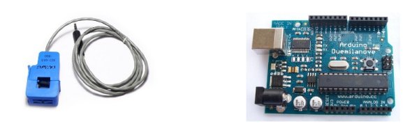
- CT sensor (example: YHDC SCT-013-000)
- Burden resistor (calculated value, e.g., 33 Ω, 39 Ω, 22 Ω, 18 Ω, 120 Ω)
- Voltage divider resistors R1 and R2 (examples: 10 kΩ, 470 kΩ)
- Capacitor C1 (example: 10 μF)
- Arduino board (example: Arduino running at 5 V)
- emonTx or emonPi hardware (examples: emonTx V2, emonTx V3, emonPi)
- Wiring/connectors for CT and Arduino
To connect a CT sensor to an Arduino, you need to adjust the CT sensor’s output signal to match the Arduino’s analog input requirements: a positive voltage ranging from 0V to the ADC reference voltage.
Note:
This page shows an example of an Arduino board running at 5 V and an EmonTx running at 3.3 V. Make sure to use the correct supply and bias voltages in your calculations that correspond to your setup.
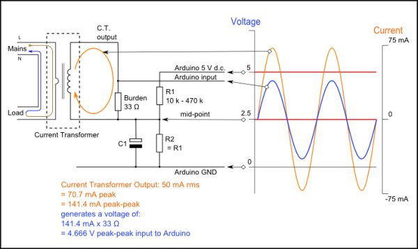
This can be done by using the following circuit, which consists of two main parts:
- The CT sensor and burden resistor
- The biasing voltage divider (R1 & R2)
Calculating a suitable burden resistor size
In the situation of a CT sensor such as the YHDC SCT-013-000 which produces current, a burden resistor is needed to change the current signal into a voltage signal. If the CT provides a voltage output, you can skip this step and forgo the burden resistor as it is already integrated into the CT.
1) Choose the current range you want to measure
The YHDC SCT-013-000 CT has a current range of 0 to 100 A so for this example let’s choose 100 A as our maximum current.
2) Convert maximum RMS current to peak-current by multiplying by √2.
Primary peak-current = RMS current × √2 = 100 A × 1.414 = 141.4A
3) Divide the peak-current by the number of turns in the CT to give the peak-current in the secondary coil.
The YHDC SCT-013-000 CT has 2000 turns and so the secondary peak current will be:
Secondary peak-current = Primary peak-current / no. of turns = 141.4 A / 2000 = 0.0707A
4) To maximise measurement resolution the voltage over the burden resistor at peak-current should be the Arduino analog reference voltage (AREF) divided by 2
If you’re using an Arduino running at 5V: AREF / 2 will be 5 V / 2 = 2.5 V and so the ideal burden resistance will be
Ideal burden resistance = (AREF/2) / Secondary peak-current = 2.5 V / 0.0707 A = 35.4 Ω
35 Ω is a rare resistor value, so we can choose between 39 Ω or 33 Ω. Choose the lower value right away to avoid the maximum load current causing the voltage to go above AREF. We recommend selecting a 33 Ω resistor with a tolerance of ±1%. Utilizing a combination of two resistors in series may occasionally result in a burden value that is closer to the ideal. The precision lessens the more the value strays from the perfect. In this situation, the peak current will result in an analog output of 4.7V (equal to 3822 when converted using a 12bit ADC).
Below are the same calculations from earlier presented in a more concise manner.
Burden Resistor (ohms) = (AREF * CT TURNS) / (2√2 * max primary current)
Burden resistor sizing for OpenEnergyMonitor energy monitoring hardware.
emonTx V3 (see guide)
The emonTx V3 uses a 3.3V regulator, so it’s VCC and therefore AREF, will always be 3.3V regardless of battery voltage. The standard emonTx V3 uses 22Ω burden resistors for CT 1, 2 and 3, and a 120Ω resistor for CT4, the high sensitivity channel. See the emonTx V3 technical wiki at: https://wiki.openenergymonitor.org/index.php?title=EmonTx_V3#Burden_Resistor_Calculations.
emonPi (see guide)
The EmonPi has two CT channels both with 22Ω burden resistors.
emonTx V2
If you’re using a battery powered emonTx V2, AREF will start at 3.3 V and slowly decrease as the battery voltage drops to 2.7 V. The ideal burden resistance for the minimum voltage would therefore be:
Ideal burden resistance = (AREF/2) / Secondary peak-current = 1.35V / 0.0707A = 19.1 Ω
19 Ω is not a common value. We have a choice of 18 or 22 Ω. We recommend using an 18 Ω ±1% burden.
Tool for calculating burden resistor size, CT turns and max Irms (thanks to Tyler Adkisson for building and sharing this).
(Note: this tool does not take into account maximum CT power output. Saturation and distortion will occur if the maximum output is exceeded. Nor does it take into account component tolerances, so the burden resistor value should be decreased by a few (~5) percent allow some “headroom.” There is more info about component tolerances at: ACAC Component tolerances.)
Adding a DC Bias
If you connect a single wire on the CT to the ground and measure the voltage on the other wire in relation to the ground, you will observe fluctuations in voltage transitioning from positive to negative in relation to the ground. However, the Arduino analog inputs require a positive voltage. Connecting the CT lead to a source at half the supply voltage rather than ground will cause the CT output voltage to fluctuate above and below 2.5 V while remaining positive.
R1 & R2 resistors in the circuit diagram serve as a voltage divider to provide a 2.5 V input (with 1.65 V allocated for the emonTx). Capacitor C1, having a reactance of just a few hundred ohms, permits the alternating current to flow around the resistor by providing a path with low impedance. A capacitance of 10 μF is suitable.
Choosing a suitable value for resistors R1 & R2
Increased resistance leads to decreased standby power usage.
Mains powered monitors are equipped with 10 kΩ resistors. The emonTx utilizes 470 kΩ resistors to ensure low power usage, as it is designed to operate on batteries for an extended period of time.
Arduino Sketch
To use the above circuit to measure RMS current, with an assumed fixed RMS voltage (e.g. 240V) to indicate approximate apparent power, use this Arduino sketch: Arduino sketch – current only
CT Sensors
In this Chapter:
For more detail: CT sensors – Interfacing with an Arduino
- How do you convert CT current output to a voltage for an Arduino?
Use a burden resistor across the CT secondary to convert current to voltage sized so peak voltage equals AREF/2. - How is the burden resistor value calculated?
Burden Resistor = (AREF * CT TURNS) / (2√2 * max primary current) as given in the article. - Can you skip the burden resistor?
Yes, if the CT provides a voltage output with an integrated burden resistor, you can skip adding one. - Why add a DC bias to the CT output?
To shift the CT AC waveform above 0V so the Arduino analog input sees only positive voltages (e.g., around AREF/2). - What values are recommended for R1 and R2 bias resistors?
Mains monitors use 10 kΩ; emonTx uses 470 kΩ for low power battery operation. - What capacitor value is suggested for the bias network?
A 10 μF capacitor is recommended to provide a low impedance AC path around the divider. - What burden resistors do emonTx V3 and emonPi use?
emonTx V3 uses 22 Ω for CT1-3 and 120 Ω for CT4; emonPi uses 22 Ω on both CT channels. - What burden resistor is recommended for emonTx V2 battery operation?
For the lower AREF at battery minimum, an 18 Ω ±1% burden is recommended. - How should you choose between nearby standard resistor values?
Choose the lower value to avoid exceeding AREF at maximum load and consider using series combinations for closer values.