Summary of Sound Reactive LED Strip Using Arduino
This Instructable shows how to build a light-reactive LED system using an Arduino and a Parallax Sound Impact Sensor to trigger LEDs (single LED, multiple LEDs, or LED strips) based on sound. It covers required components, breadboard wiring basics, sensor sensitivity adjustment, and using Arduino PWM to control LED brightness. The project is inexpensive, reusable, and adjustable for different LED types and layouts.
Parts used in the Light Reactive LED System:
- LED (single color strip used in article)
- Mini breadboard
- Arduino Uno
- Solid core wire
- USB A to B cable
- Wire cutter/stripper
- Parallax Sound Impact Sensor
- Wall adapter power supply - 9VDC 650mA
THERE MAY BE 9 STEPS BUT I PROMISE THIS ONE IS QUICK AND EASY!
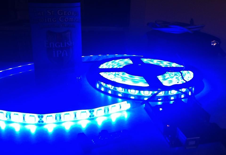
In this Instructable I will be showing you how to create a light reactive LED system. In this clip, I used a single color LED strip, but you you can use a single LED, multiple LEDs wired together, single color or RGB LED strip, it just depends on what you are trying to build. The set up is fairly simple, the component list is fairly basic so if you are a tinkerer you should already have the majority of the materials laying around. If not, I will post links to the components I used so you can order parts and get to work!
In the following link you will see the entire setup. Obviously you may arrange it anyway you would like, I just kept everything close and compact for the sake of an easy video.
Step 1: Components
For this project you will need the following:
1) LED ~$20 (with shipping)
– For this project I used a solid blue LED strip which I purchased on amazon. These 5 meter SMD 5050 strips can run around $70 in retail stores so I though I would be taking a chance purchasing something priced under $20, but I was not disappointed in the least. I’m sure there are better quality lights out there, but if you plan on cutting these up and have no real game plan you wont feel any guilt putting these through the ringer.
2) Mini breadboard $5
3) Arduino Uno $30
4) Solid core wire $2.50
– For anything involving breadboarding, do yourself a favor and stay away from any stranded wire. It will just end up getting frayed and hard to manage. Solid core is the way to go. I also like to choose at least two different colors for my wire to keep grounds and powers visibly separate. It makes troubleshooting and wiring easier in the long run when dealing with a lot of components.
5) USB A to B cable $4
– This will be used to upload your Arduino LED code to the Arduino Uno board
6) Wire cutter/stripper $5
7) Parallax Sound Impact Sensor $10
8) Wall Adapter Power Supply – 9VDC 650mA $6
Total cost will be a bout $80 but keep in mind, all of these components are completely reusable. You can recycle them into a multitude of projects in the future so try not to worry about the cost. Think of it as building up your technical tool box 🙂
Step 2: Breadboard Basics
Breadboards are incredibly helpful when building circuits. They help you keep all of your components organized and laid out in a logical fashion. They also make it easy to confirm that the right wires are making the connections to the proper component leads. If you have never worked with a breadboard before, I’ll explain the internal connection layout with the diagram above:
The on either side of the breadboard there are two columns, denoted by the blue and red highlights. These columns allow the user to have a common power and ground for components no matter where they are placed on the board. Whether your component is placed at A1 or J30, a common power and ground connection will only be a short distance away. All of the holes are connected vertically, so if you connected your ground (or power if you felt so inclined) to the left or right most blue column, your common ground would extend from that column from position 1 all the way down to 30. However, the left and right sides are not connected, so If you wanted both blue columns grounded you would need to make two separate connections on either side.
Rows A-E and F-J are where your components will be placed. This part of the board is also split between the left and right side about the center of the board. If a wire is placed in A1, that charge will carry through E1 and stop at the center divide. If a wire is placed in F1 that charge will carry through J1. You do not have to start out at position 1 every time either. If you place a connection at C1 for example, A1, B1, D1 and E1 would all have the same charge.
TL; DR
The first two and last two blue and red columns share a connection vertically.
A-E share a connection horizontally
F-J share a connection horizontally
A-E connections and F-J connections are not bridged across the center.
Step 3: Parallax Sound Impact Sensor
Once the microphone picks up a sound that is above the sensitivity threshold, the sensor sends a high (1) signal from the SIG line to whatever component you are trying to connect.
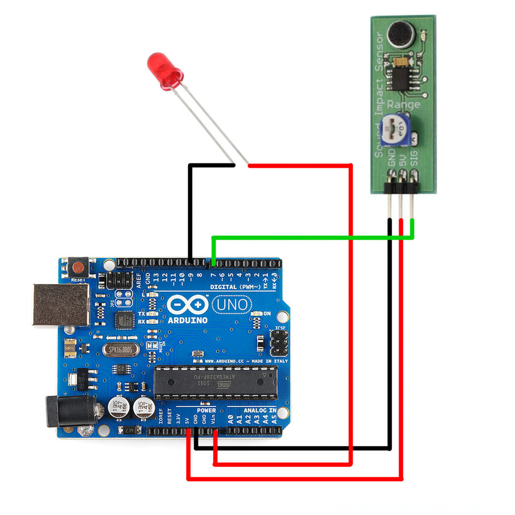
Step 4: Arduino and Pulse-Wave Modulation
An Arduino Uno is perfect for this project because it can handle the load of the LED strip, you can write multiple programs depending on what particular behavior you would like to see from your LEDs and besides the standard General Purpose Input/Output (GPIO) pins, it also has Pulse-Width Modulation (PWM) pins. PWM pins are great for powering components such as LEDs and electronic motors and although the pulse wave forms may look a bit jumpy (from the pulsating ons and offs) it actually allows you to control aspects such as brightness (when it comes to LEDs) and speed (when it comes to motors) in a very deliberate. smooth fashion, while efficiently utilizing your power.
Here is a nice explanation of Pulse-Wave Modulation from the awesome people of MAKE (makezine.com)
For more detail: Sound Reactive LED Strip
- What does this project build?
A light-reactive LED system that triggers LEDs based on sound using an Arduino and a Parallax Sound Impact Sensor. - Can I use different types of LEDs?
Yes, you can use a single LED, multiple LEDs wired together, single color or RGB LED strips. - What sensor detects the sound?
The Parallax Sound Impact Sensor detects sounds above a sensitivity threshold and outputs a SIG signal. - How do I adjust the sensor sensitivity?
The sensor has a dial that lets you fine tune sensitivity for quieter or louder sounds. - Why use an Arduino Uno for this project?
The Arduino Uno can handle the LED load, supports GPIO control, and provides PWM pins for smooth brightness control. - What is PWM used for in this project?
PWM (Pulse-Width Modulation) controls LED brightness by rapidly switching power on and off to create smooth brightness levels. - Do I need a breadboard?
A mini breadboard is used to organize components and make wiring and troubleshooting easier. - What power supply is required?
The project uses a 9VDC 650mA wall adapter power supply.