Summary of Crafting Your Unique Arduino Creation: A DIY Project Guide
Build your own Arduino on a solderless breadboard using an ATmega168/328, a 7805 regulator for +5V from a >5V source (e.g., 9V battery), support capacitors, crystal or resonator with capacitors, reset switch and pullup, LED indicator, and programming header wired to a USB-TTL adapter. Power rails should be bridged left/right. Configure IDE board type and COM port, upload the Blink sketch while resetting at upload, then run from battery. Troubleshoot power, wiring, and upload errors via Arduino resources.
Parts used in the Build Your Own Arduino:
- ATmega168 or ATmega328 microcontroller
- Solderless breadboard
- 7805 voltage regulator
- 9V battery with snap connector (or other >5V supply)
- 10uF capacitors (two)
- 0.22uF capacitors (two .22pF noted in article—use as specified)
- 16MHz crystal (or 16MHz ceramic resonator three-terminal SIP)
- 16MHz resonator (alternative option with built-in caps)
- 10K resistor (pull-up for reset)
- 220 ohm resistor (LED series resistor)
- LED for status indicator
- Tact switch (reset button)
- Male header pins (row of six for programming header)
- Hook-up jumper wires (various colors for power, ground, signals)
- USB-TTL programming cable or breakout (TTL-232R cable, FT232RL breakout BOB-0071, or FTDI Basic Breakout DEV-08772)
Build Your Own Arduino
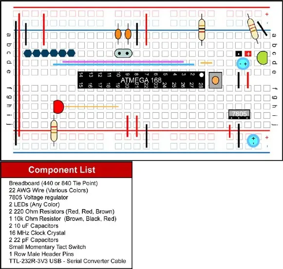
Power setup with LED indicator.
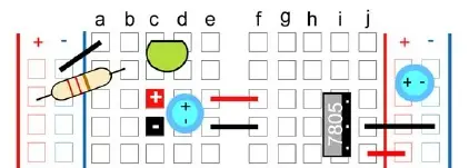
To activate the voltage regulator, a power supply exceeding 5V is required. A typical 9V battery with a snap connector is well-suited for this purpose. Power will be introduced into the breadboard via designated red and black terminals.
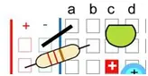
Begin by placing one of the 10uF capacitors across the designated squares on the breadboard. Note that capacitors have a longer leg known as the Anode (Positive) and a shorter leg referred to as the Cathode (Negative), often marked with a stripe. Position the capacitor accordingly.
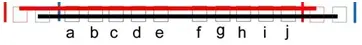
To bridge the gap across the breadboard’s empty space, insert two hook-up wires—one for positive (red) and one for ground (black)—to ensure continuous power flow.
Next, insert the 7805 voltage regulator, which features three legs. When viewed from the front, the left leg corresponds to voltage in (Vin), the middle leg is for ground (GND), and the third leg is for voltage out (Vout). Align the left leg with the positive power input and connect the second leg to ground.
Connect a ground wire from the voltage regulator to the ground rail on the breadboard, and then connect the Vout wire (third leg of the voltage regulator) to the positive rail. Attach the second 10uF capacitor to the power rail, ensuring correct orientation based on the Positive and Negative markings.
For troubleshooting purposes, it’s advisable to incorporate an LED status indicator. To achieve this, connect the power rails on the right and left sides of the breadboard, pairing positive with positive and negative with negative wires at the bottom of the breadboard.
Having power on the left and right power rail will also help to keep your breadboard organized when providing power to the various components.
Well done, your breadboard is now configured to receive +5V power. You’re ready to proceed to the next phase of the circuit design. Our next task is to prepare the ATmega168 or 328 chip. Before we delve into this, let’s examine the function of each pin on the chip in relation to Arduino functions. Please note: While the ATmega328 operates at a similar speed and has the same pinout, it boasts over twice the flash memory (30k vs. 14k) and double the EEPROM (1Kb vs. 512b).
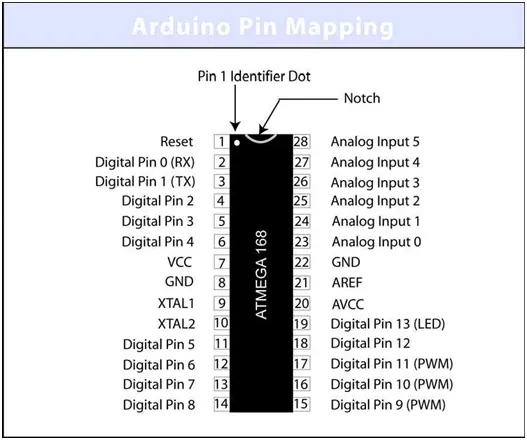
The ATmega168 chip, manufactured by Atmel, may not correspond precisely to the references provided above if you consult its datasheet. This discrepancy arises because Arduino has its own pin functions, which I’ve outlined solely for this illustration. For accurate pin references or comparison, you can obtain the datasheet from www.atmel.com. With an understanding of the pin layout, we can proceed to connect the remaining components.
Firstly, we’ll establish the support circuitry for one side of the chip before addressing the other side. Pin one of most chips is typically marked with an identifier. Examining the ATmega168 or 328, you’ll observe a u-shaped notch at the top alongside a small dot, indicating pin 1.
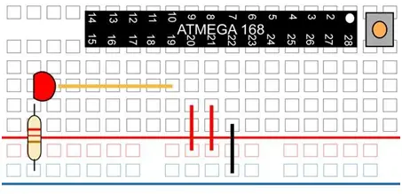
Start by connecting a jumper wire from the GND power bus to pin 22. Then, extend jumper wires from the positive power bus to pin 20 (AVCC), which supplies voltage to the ADC converter. It’s essential to connect this pin to power, whether or not the ADC is in use. Additionally, attach another jumper wire from the positive bus to pin 21, serving as the analog reference pin for the ADC.
On the Arduino, pin 13 serves as the LED pin. Although the pin number on the actual chip is 19, you will consistently reference it as Pin 13 when uploading your sketch code and for all projects.
To connect the LED, incorporate a 220Ω resistor bridging from GND to the cathode of the LED. Then, connect a jumper wire from the anode of the LED to pin 19.
Transitioning to the other side of the chip, your setup is nearly complete!
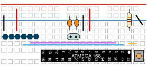
Position the small tact switch above the ATmega168 chip, close to the pin 1 marker. This switch serves as the Arduino reset button. Prior to uploading a new sketch to the chip, press this switch once.
Connect a small jumper wire from pin 1 to the lower leg of the switch. Then, attach the 10K resistor from power to the pin 1 row on the breadboard. Finally, connect a GND jumper wire to the upper leg of the switch.
Attach power and GND jumpers to pin 7 (VCC) and pin 8 (GND). Install the 16MHz clock crystal to pins 9 and 10, followed by connecting two .22pF capacitors from pins 9 and 10 to GND.
Your basic breadboard Arduino setup is now assembled. While you could stop here and transfer a pre-programmed chip from your Arduino board to the breadboard, it’s recommended to proceed with adding programming pins for flexibility.
Alternatively, instead of using the 16MHz clock crystal, you can opt for a 16 MHz ceramic resonator with built-in capacitors, three-terminal SIP package. In this case, arrange your breadboard differently, with the resonator’s middle leg connected to ground and the other two legs to pins 9 and 10 on the ATmega168 chip.
Identify a space on the breadboard with six columns not in contact with other components. Insert a row of six male header pins here, labeled as follows from left to right: GND, NC, 5V, TX, RX, NC (or pins 1, 2, 3, 4, 5, 6).
From the power bus rail, connect the GND wire to pin 1 and a wire from power to pin 3. The NC pins (not connected) can be linked to GND if desired.
Connect a wire from pin 2 on the ATmega168 chip (Arduino RX pin) to pin 4 (TX) on the programming headers. Likewise, connect pin 3 (Arduino TX) on the ATmega168 chip to pin 5 (RX) on the header pins.
The communication setup is as follows: ATmega168 RX to Header Pin TX, and ATmega168 TX to Header Pin RX. Now your breadboard Arduino is ready for programming.
Programming Options
The initial choice is to acquire a TTL-232R 3.3V USB – TTL Level Serial Cable, which is available for purchase on websites such as www.adafruit.com or www.ftdichip.com.
Alternatively, I recommend two other options, both of which are breakout boards offered by SparkFun.com. These options include:
– FT232RL USB to Serial Breakout Board, identified by SKU: BOB-0071. Please note that this choice occupies more space on your breadboard.
– FTDI Basic Breakout – 3.3V, designated by SKU: DEV-08772. This option, especially when paired with right angle male headers, proves to be the most effective among the three as it offers better stability on the breadboard.
Build Your Own Arduino
Verify your connections thoroughly, ensuring the 9V battery remains disconnected, and establish your programming setup. Launch the Arduino IDE and navigate to the Example sketch files, located under Digital. Load the Blink sketch.
From the file menu, access Serial Port and select the appropriate COM port corresponding to your USB cable connection (e.g., COM1, COM9, etc.).
In the file menu under Tools/Board, choose one of the following options based on your breadboard Arduino configuration:
• Arduino Duemilanove w/ATmega328
• Arduino Decimila, Duemilanove, or Nano w/ATmega128 (depending on the chip used with your breadboard Arduino)
Now, click the upload icon and proceed to press the reset button on your breadboard. If you’re utilizing one of the SparkFun breakout boards, observe the RX and TX lights blinking, indicating data transmission. Occasionally, allow a few seconds after clicking the upload button before pressing the reset switch. If encountering difficulties, experiment with timing between the two actions.
Once the sketch uploads successfully, the LED on pin 13 will blink in a one-second on, one-second off pattern until either a new sketch is uploaded or the power is turned off.
After code upload completion, you can disconnect the programming board and rely on your 9V battery for power.
Troubleshooting
• Insufficient Power – Ensure that your power source supplies voltage higher than 5V.
• Power On, No Functionality – Double-check all connections to ensure proper connectivity.
• Upload Error – Consult www.arduino.cc and search for the specific error message encountered. Additionally, explore the forums for valuable assistance and troubleshooting tips.
- What power supply is required for the breadboard Arduino?
The article specifies a power source higher than 5V, with a typical example being a 9V battery and snap connector feeding a 7805 regulator. - How do you get +5V on the breadboard?
Use a 7805 voltage regulator with input from a >5V supply, connect input to Vin, ground to GND, and Vout to the positive rail, plus two 10uF capacitors on the input and output. - Which chip pins need power and ground connections?
Connect pin 7 to VCC (power) and pin 8 to GND; also connect pin 20 (AVCC) and pin 21 (Aref) to the positive power bus and pin 22 to ground. - How is the LED on Arduino pin 13 wired?
Connect a 220 ohm resistor from GND to the LED cathode, and wire the LED anode to chip pin 19 (Arduino digital pin 13). - How is the reset circuit implemented?
Place a tact switch with one leg to pin 1 via a jumper, the other leg to GND, and use a 10K resistor from power to the pin 1 row as the pull-up. - What clock options are recommended for the ATmega chip?
Use a 16MHz crystal with two .22pF capacitors to GND, or a 16MHz ceramic resonator three-terminal SIP as an alternative. - How should programming headers be wired to the chip?
Install six header pins labeled GND, NC, 5V, TX, RX, NC; connect GND and 5V to power rails, and wire ATmega RX to header TX and ATmega TX to header RX. - What USB-TTL programming options are suggested?
The article recommends a TTL-232R 3.3V USB-TTL cable, SparkFun FT232RL USB to Serial Breakout BOB-0071, or SparkFun FTDI Basic Breakout DEV-08772. - How do you upload code to the breadboard Arduino?
Select the appropriate COM port and board type in the Arduino IDE, click upload, then press the breadboard reset button (timing may need adjustment) to transfer the sketch. - What troubleshooting steps are recommended for upload errors?
Check that the power source is >5V, verify all wiring connections, and consult www.arduino.cc and forums for specific error messages and help.