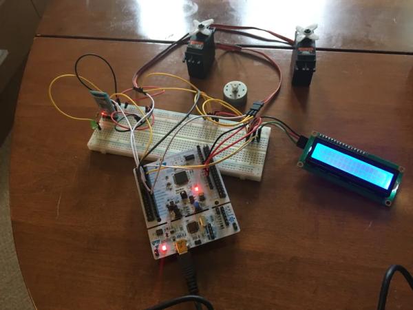
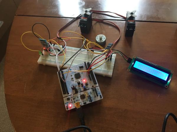
In this project we will use an iPhone to control devices connected to an STM32 device. The project is a starting point for more exciting experiments such as remote controlled robots or any other thing you might want to control in your home. I encourage you to check out the source code which is really very minimal at the moment and has plenty of scope for extension. If you like it and want to contribute to the project on github please let me know. Otherwise just use it or fork from it and build your own projects.

Step 1: Parts List
Hardware
- An STM32 Nucleo-64 development board – http://www.st.com/en/evaluation-tools/nucleo-f401r…
- A simple two line LCD – something like this – https://www.amazon.co.uk/KOOKYE-solderless-Charact…
- A BLE module – https://www.amazon.co.uk/qobobo-Bluetooth-Wireless…
- A LED and small Resistor to protect it against the 5V
- A prototype breadboard and some wires with square connectors and pin connectors at the ends
- Some things to control, LED’s, DC motors, Servo motors, Brushless motors with ESC’s etc
- An iPhone or iPad
- A mac to build the iOS project on
Software
- ST-Link V2 Driver – http://www.st.com/en/development-tools/st-link-v2…
- STM32CubeMX – http://www.st.com/content/st_com/en/products/embed…
- STM32 System Workbench IDE -http://www.st.com/content/st_com/en/products/development-tools/software-development-tools/stm32-software-development-tools/stm32-ides/sw4stm32.html
- Xcode – https://itunes.apple.com/gb/app/xcode/id497799835?…
Step 2: Download Source Code
Download the code I’ve developed for the project.
Actually it is two different projects, one is a swift project for the iPhone/iPad app side and the second is the code for the STM32F401RE Nucleo board.
Here are links which I’ve open sourced them on Github:
https://github.com/DanXS/BLEControl – swift code
https://github.com/DanXS/BLE_LCD_PWM – nucleo code
Step 3: Load the STM32CubeMX Project

Start the STM32CubeMX application
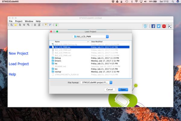
You will be given the choice of creating a project or loading an existing project. In this case we will just load our existing project just to have a look at what the UI looks like and what its about.
Click load and locate the project file from the BLE_LCD_PWM project folder you downloaded from github earlier. The project file is called BLE_LCD_PWM.ioc
Once loaded you will see there are a number of tabs along the top, The first one show the chip and the pinout. The green ones are the pins we are using which will map to breakout pins on the Nucleo boards – (well mostly), some are not connected, so be careful to check the diagram which comes with the Nucleo board. Hovering over a pin will show the port and pin number so you can figure out the location on the board.
For this project the pins used are also listed in the BLE_LCD_PWM.pdf file which is generated automatically when you click Generate Report from the UI.
The next screen is for configuring the clock rates as well as the ability to select an external clock source. You don’t need to do anything here, just know its there and that is what it is for.
Next you have Configuration Screen – here you will see that it has sections, under connectivity you will see it has I2C2 and UART1, these are what I’m using to connect to the LED (I2C2) and the bluetooth module (UART1).
Normally you would configure everything in here and then click Generate Project to generate the source code and startup configuration code for your base project. But we already have one here so there is no need.
Close out of the project for now.
Step 4: Wire Up Comms

Start with the power
On the right hand side of the board you will see some power pins. It has both 5v and 3.3v and a some ground lines. Connect the ground and 5v lines to the prototype board power lines. The 3.3v is need for the lcd as it is designed for 3.3v not 5v. Connect the 3.3v line to somewhere else on the board so you can connect it to the LCD.
Connect up the Bluetooth module, the module has 6 connectors but we are only using 5 of them here.
- STATE – This is an output line that indicates that bluetooth is connected
- RXD – This is the UART data input pin to the module
- TXD – This is the UART data output pin from the module
- GND – Ground
- VCC – Voltage line
Insert the Bluetooth module to some unconnected lines on the breadboard
- Connect the VCC and GND pins to the power rails
Connect the the LED and Resister in series to the STATE pin and then back to ground – this will show us when the iPhone connects with bluetooth.
Now the data lines:
- The RXD should go to USART1_TX on the Nucleo – Pin PA9
- The TXD should go to USART2_RX on the Nucleo – Pin PA10
Notice they are crossed over, this is because the Bluetooth module receives from the transmitted data from the Nucleo and transmits what it receives from the Nucleo.
Next connect up the LCD.
Start with the power lines, remember this time the VCC line should go to 3.3v not 5v.
- Connect the VCC to the 3.3v line
- The GND goes to the same (Common) ground – you only ever need one ground.
The other two pins are for I2C, which is a common communication protocol developed by Phillips – https://en.wikipedia.org/wiki/I%C2%B2C
Here we have SCL and SDA pins, the first is for the clock which is driven from the master – (The Nucleo) and the second is the data line.
This time they share a data line and a clock line, so there is no crossover.
- Connect SCL to I2C2_SCL – pin PB10
- Connect SDA to I2C2_SDA – pin PB3
Step 5: Wire Up Some Motors or Other Gizmos
Next connect up some motors – I had a few servos and a little DC motor I’d salvaged out of something to try out. You can also wire up some LED or other devices as you see fit.
Currently the software uses 8 PWM outputs, on the swift side I’ve used the first 4 sliders for Servo/Brushless motor signals and the next 4 sliders for general voltage varying PWM channels.
The main difference is that the a servo expects a 20ms PWM signal with the pulse width being 1ms to 2ms long while to vary voltage the full 20ms interval can be used. The idea is that if the square wave is mostly high it seems to the LED or DC motor like it is just a high voltage and if it is mostly low it seems like a low voltage when you sum it all up over time. Although in fact it is not a smooth voltage but a square wave, but at that rate of change it doesn’t matter too much to the device although you can use a capacitor and a resistor to smooth out the signal.
The 8 PWM channels I’ve used on the Nucleo (STM32F401RE) project are driven by two timers. I chose the timers base on the pins they used and the number of PWM signals they can support. The way it works basically is that each timer has associated counters which increase all the time, but you can set the time at which it should reset and start counting up again thus controlling the pulse width.
Here is how the 8 signals are configured:
- TIM3_CH1 – pin PA6
- TIM3_CH2 – pin PA7
- TIM3_CH3 – pin PB0
- TIM3_CH4 – pin PB1
- TIM4_CH1 – pin PB6
- TIM4_CH2 – pin PB7
- TIM4_CH3 – pin PB8
- TIM4_CH4 – pin PB9
Remember the first 4 are configured within the iOS application to Servo signals while the next 4 are designed for other analog like PWM signals, so make sure you don’t try to drive a Servo with the wrong signal.
One tool I would really recommend is a signal analyser, you can get very expensive professional ones but also really cheap ones that do the job fine for most situations. I used it to make sure that the PWM signals coming from the device look as they should before feeding them into anything.
In this example I’ve used directly wired up servo’s to the same 5v lines that are used to power the board, in practice this isn’t a great idea as the servo’s usually need about 6v and eat up a lot of amps – if you have another power source power the motors with them instead ideally. If you are using brushless motors you will likely need a lot more voltage still, so really they wouldn’t run at all from the 5v power lines. You would use a higher voltage supply to the motor while still using the same signal voltage for controlling the brushless motor via an electronic speed controller (ESC).
Step 6: The Software
First for the STM side of things:
Open the BLE_LCD_PWM project into the System Workbench for STM32 IDE which is essentially Eclipse with some extra plugins installed specially for STM development, you can use an existing version of Eclipse if you have one and add the plugins, but it is more work and you need OpenOCD as well which is used to debug STM applications via the USB connection or an ST-Link if you are using one of those on a different board without a USB connection. The Nucleo has a USB port so no and the ST-Link part of things on a as part of the board – the bit that of the board which looks partially connected to the main board. You can actually snap it off when you want to save space and use the STM32F401RE part in a project and don’t intend to debug or change the software.
As the project already exists you may have to import the project via the import project into workspace route – which is a bit of a wired way that Eclipse likes to do things – I really don’t like that, why can’t you just load a project where it is, what is the workspace business all about anyway – horrible design but apart form that Eclipse isn’t a bad IDE.
Connect up the board and run or debug the project, when you choose debug it will offer you the choice to go into the debugging perspective and will automatically put a breakpoint at the start of the main function, you will need to hit the play/pause button to start it running, but you can also put breakpoints elsewhere in the project and view how it works.
Basically it receives interrupts from the UART/Bluetooth Module as bytes arrive and places them in a circular buffer. Meanwhile the main thread reads from the buffer and interprets and runs the commands which are a very minimal protocol.
So far the protocol just has a few commands, but could can be extended to support more features – this I intend to do in the future as I discover how to control more devices from STM32 MCU.
You could if you like implement this protocol into a different device such as an Arduino or Raspberry Pi. Likewise it doesn’t have to run through the bluetooth module, you could communicate from your laptop via a USB to UART converter which would no doubt be much faster.
Now for the Swift/iOS/Xcode side:
- Open the other project, BLEControl
- Connect up your iPhone or iPad and select it as the target.
- Click run to install the application on your device.
You may get errors regarding the application identifier and/or provisioning profile as you generally do when you use projects from other authors, so you might need to go in and change them so that they match your normal credentials.
To use the application, first click on scan, this will look for your bluetooth module, if everything goes well you should see a device called BT-05 come up or something similar, click on it to connect. Now you should be able to drive your motors etc with the phone.
Have a look at the attached youtube vid to see it in action. Also on the swift side of things, it is really quite easy to port to your own projects that do more than just present sliders, for example to drive a robot around or whatever you want to do. Basically the view controllers in the project just demonstrate the bluetooth and the custom protocol. But the files in the BLE folder can be used for other projects, adding new commands to the protocol should also be quite easy – just add them the the Commands enum and create some methods to build and send them on to the bluetooth device in the same way that the other commands are sent. The readme on Github provides more information.
Source: Controlling Devices in Swift With BLE
