Summary of Wireless LED driver with PCA9634
This article details a project to drive LEDs via RF using the PCA9634 chip and an IQRF TR-52D module. The author tested a custom breakout board, developed a low-level driver, and plans to release a PC application for control. The PCA9634 supports RGBA color mixing with individual and group PWM controllers, operating between 2.3 V and 5.5 V.
Parts used in the Wireless LED Driver Project:
- PCA9634 chip
- IQRF TR-52D module
- Custom PCA9634 breakout board
- Schematic with pull-ups and pull-downs
- I2C connectors
- Output connectors
- Power supply indication LED
- Resistor for power indication
f You are interested in LED driving through RF, this article would be interesting for you. I tested own PCA9634 breakout board for this chip and wrote simple low level driver for IQRF TR-52D module. Next week, I am going to publish PC application for comfortable operation with that.
About PCA9634 (from datasheet)
The PCA9634 is an I2C-bus controlled 8-bit LED driver optimized for Red/Green/Blue/Amber (RGBA) color mixing applications. Each LED output has its own 8-bit resolution (256 steps) fixed frequency Individual PWM controller that operates at 97 kHz with a duty cycle that is adjustable from 0 % to 99.6 % to allow the LED to be set to a specific brightness value. An additional 8-bit resolution (256 steps) Group PWM controller has both a fixed frequency of 190 Hz and an adjustable frequency between 24 Hz to once every 10.73 seconds with a duty cycle that is adjustable from 0 % to 99.6 % that is used to either dim or blink all LEDs with the same value.
Each LED output can be off, on (no PWM control), set at its Individual PWM controller value or at both Individual and Group PWM controller values. The LED output driver is programmed to be either open-drain with a 25 mA current sink capability at 5 V or totem-pole with a 25 mA sink, 10 mA source capability at 5 V. The PCA9634 operates with a supply voltage range of 2.3 V to 5.5 V and the outputs are 5.5 V tolerant. LEDs can be directly connected to the LED output (up to 25 mA, 5.5 V) or controlled with external drivers and a minimum amount of discrete components for larger current or higher voltage LEDs..
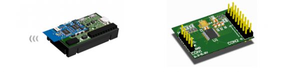
PCA9634 Breakout Board
Breakout board is based around PCA9634. Full schematic is below. There are only PCA9634, pull-ups, pull-downs for SDA, SCL, OE lines and address lines, and connectors for I2C and outputs. There are also LED and resistor for power supply indication
Breakout board is made on two side PCB. Gerber files are available at the end of post.
For more detail: Wireless LED driver with PCA9634
- What is the primary function of the PCA9634 chip?
The PCA9634 is an I2C-bus controlled 8-bit LED driver optimized for Red/Green/Blue/Amber color mixing applications. - How many bits of resolution does each LED output have?
Each LED output has its own 8-bit resolution providing 256 steps. - Can the PCA9634 operate with external drivers?
Yes, LEDs can be controlled with external drivers and a minimum amount of discrete components for larger current or higher voltage requirements. - What modules are used for RF LED driving in this project?
The project uses the IQRF TR-52D module for wireless communication. - Does the PCA9634 support dimming all LEDs simultaneously?
Yes, it features an 8-bit Group PWM controller used to dim or blink all LEDs with the same value. - What is the supply voltage range for the PCA9634?
The device operates with a supply voltage range of 2.3 V to 5.5 V. - What future component will the author publish next week?
The author plans to publish a PC application for comfortable operation with the system.