You can control your MKR1000 remotely with a RESTFUL interface.
Things used in this project
Hardware components |
||||||
 |
|
× | 1 | |||
 |
|
× | 2 | |||
 |
|
× | 2 | |||
 |
|
× | 5 | |||
Software apps and online services |
||||||
 |
|
|||||
Story
It would be nice to communicate with an Arduino thru RESTFUL interface and I found this aREST framework. As described on its website (arest.io), the aREST framework is a complete solution to build powerful RESTful applications based on the Arduino & the Raspberry Pi platforms. It can handle all kind of communications via Serial, WiFi, Ethernet, and much more.
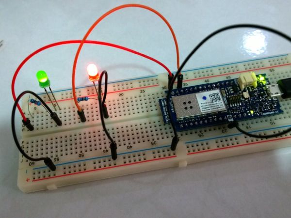
In this project, I will show how to setup MKR1000 with 2 LEDs and you can control the LEDs via REST API.
Steps to setup the dev environment
1. Setup the MKR100 using this Getting Started guide.
2. Install Wifi101 library using Sketch > Include Library > Manage Libraries …menu. (Note: I am using Wifi101 version 0.9.0)
3. Install aREST library. (Note: I am using aREST version 2.1.1)
4 Make the following changes to aREST.h:
- Change
WiFi_htoWIFI_H - Change the following
void addToBuffer(float toAdd) {
  char number[10];
  dtostrf(toAdd, 5, 2, number);
  addToBuffer(number);
}
to
void addToBuffer(float toAdd) {
  char number[10];
  sprintf(number, "%5.2f", toAdd);
  addToBuffer(number);
}
5. Copy the sketch from the code section below.
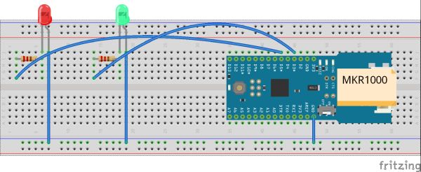
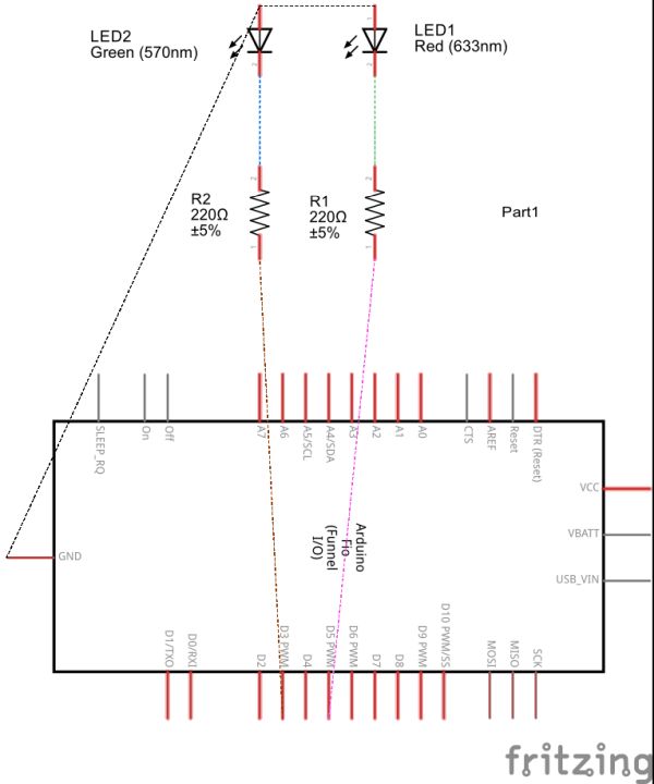
6. Setup the board and LEDs.
7. Compile and upload the sketch.
About the sketch
Creating a WiFiServer instance listening to port 80:
WiFiServer restServer(80);
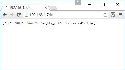
Setting the device ID and name:
// Give name and ID to device
rest.set_id("008");
rest.set_name("mighty_cat");
The loop() is simple, just listening to port 80 and handling incoming connection:
void loop() {
  // Handle REST calls
  WiFiClient client = restServer.available();
  rest.handle(client);
}
Exposing the custom function ledControl(String) within setup():
// Function to be exposed
rest.function("led",ledControl);
This is the ledControl(String) function:
// Custom function accessible by the API
int ledControl(String command) {
  Serial.println(command);
  // Get state from command
  int state = command.toInt();
  digitalWrite(5,state);
  return 1;
}
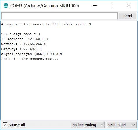
Finally the printWifiStatus() function:
void printWifiStatus() {
  // print the SSID of the network you're attached to:
  Serial.print("SSID: ");
  Serial.println(WiFi.SSID());
  // print your WiFi shield's IP address:
  IPAddress ip = WiFi.localIP();
  Serial.print("IP Address: ");
  Serial.println(ip);
  IPAddress subnet = WiFi.subnetMask();
  Serial.print("Netmask: ");
  Serial.println(subnet);
  IPAddress gateway = WiFi.gatewayIP();
  Serial.print("Gateway: ");
  Serial.println(gateway);
  // print the received signal strength:
  long rssi = WiFi.RSSI();
  Serial.print("signal strength (RSSI):");
  Serial.print(rssi);
  Serial.println(" dBm");
}
Running the sketch
Open the Serial Monitor using Tools > Serial Monitor menu and note down the IP address shown.
Display the device ID and name:
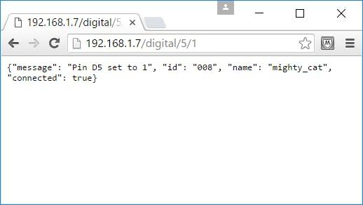
To turn on pin 5, type the following to the web browser:
http://<ip-address>/digital/5/1
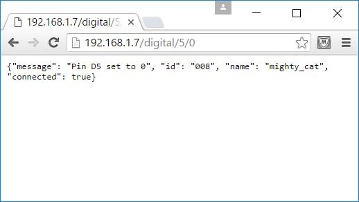
To turn off, type
http://<ip-address>/digital/5/0
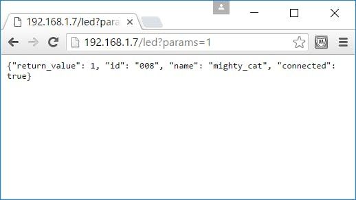
To turn on using exposed function, type
http://<ip-address>/led?params=1
To Find out More About aREST
Refer to the aREST Arduino library page on GitHub
Schematics
Code
Source : Control your MKR1000 with aREST Framework