In one of my previous Instructables, I showed you how you can use a Stepper motor as a rotary encoder. In this Instructable, let’s learn how we can use it to control our computer. So without further ado, let’s get started!
Step 1: Watch the Video
Watch the above video to get a better idea of what it is all about and what to do.
Step 2: Get All the Required Stuff
For this project, you will need:
- A USB HID(Human Interface Device) compliant Arduino microcontroller board(Leonardo, Micro, Pro Micro)
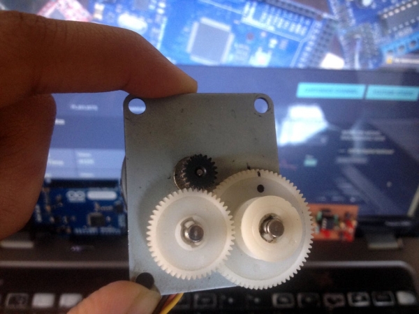
- A stepper motor*.
- A stepper motor to rotary encoder converter.
- A suitable USB cable(Usually micro USB to A)
- 2 pairs of male to female wires(For connecting the rotary encoder board to the Arduino board)
- A set of 3 male to female wires(For connecting the stepper motor to the rotary encoder board)
*Any stepper motor, unipolar or bipolar can be used in the project. A unipolar stepper motor is recommended as it has straightforward wiring but a bipolar stepper motor can also be used with a tiny change in wiring.
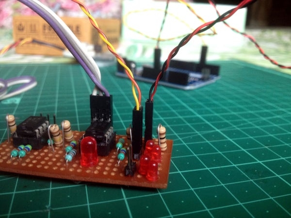
Step 3: Make the Rotary Encoder Board
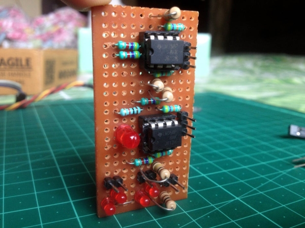
Click on the above image to know more.
Follow this Instructable to make the rotary encoder converter. You can make a breadboard version but a permanent PCB version is more compact, durable and can help you practice some soldering. You can also add an LED on each output of the amplifier board, in series with a resistor(220 Ohm recommended) to monitor the output states of the amplifier which can prove useful while troubleshooting.
Step 4: Program the Arduino Microcontroller
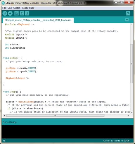
It recommended going through the Arduino code before uploading it on the microcontroller board. It can help you understand what all is going on inside the microcontroller when you are rotating the stepper motor.
Step 5: Connect the Stepper Motor to the Rotary Encoder Board
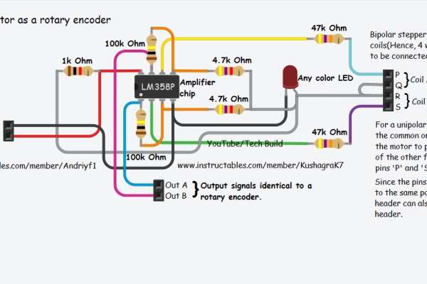
Make sure you through the circuit schematic carefully.
If a unipolar stepper motor is being used then connect the center tap wire of the motor to either of the pins ‘Q’ or ‘R’. Then, connect any two of the four remaining wires of the stepper motor to the pins ‘P’ and ‘S’ respectively. Here, I have used a 1×3 header instead of the 1×4 shown in the schematic.
If a bipolar stepper motor is being used, first determine the coil pair wires of the motor. Then take a wire from each coil and connect them together to either of the pins ‘Q’ or ‘R’. Then, connect the remaining two wires of the stepper motor to the pins ‘P’ and ‘S’ respectively.
Step 6: Connect the Rotary Encoder Board to the Arduino Board
- Connect the +ve and -ve pins of the rotary encoder board to the +5-volt and ‘GND’ pin of the Arduino board respectively.
- Connect the output pins of the rotary encoder board to the digital pins ‘D5’ and ‘D6’ of the Arduino board.
Step 7: Connect the Setup to Your Computer and Test It
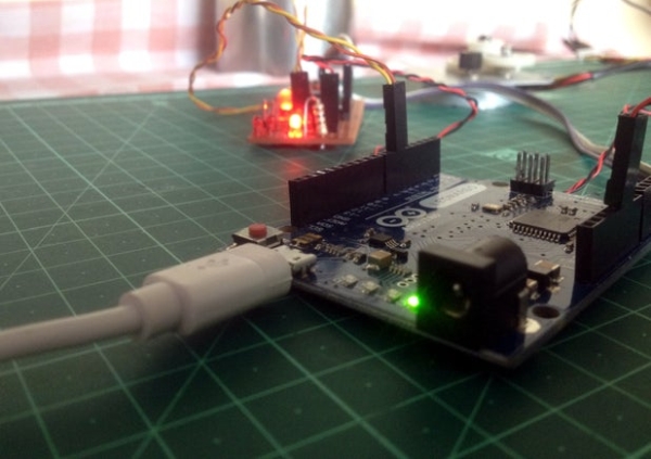
Connect the setup to your computer and open any program which allows the user to either scroll up and down using arrow keys or a program where the text cursor can be moved using the arrow keys.
Source: Control Your Computer With a Stepper Motor!