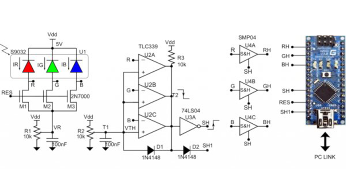
The Design Idea in Figure 1 is a color detector capable of generating an RGB triplet over a high dynamic range, a useful attribute for machine vision applications. The circuit implements auto-exposure control to achieve this. Thus, RGB values for a subject are invariant over a range of light intensity.

The three common-cathode RGB photodiodes (U1) are reverse‑biased and pre-charged to VR (typically 0.5V) through the three N-channel MOSFETs (M1, M2, M3) when RES is driven high by the µC (microcontroller). After the reset phase, the voltages on nodes R, G, and B start increasing, linearly proportional to the intensity of each color component. These signals feed three comparators (U2) with wired-OR-connected outputs. The first signal reaching the threshold VTH (typically 2.6V) causes SH to assert through inverter U3A, which strobes the sample-and-hold amplifiers, U4.
The held voltages RH, GH, and BH are then converted by the Arduino Nano for further processing. Analog-to-digital conversion could be accomplished by the µC without U4, but the successive conversions would introduce a sampling error among signals. This error is larger for brighter signals because of the higher slew‑rate. Alternatively, a µC with at least three ADCs could be used.
D1 adds brute-force hysteresis to the comparators, and D2 allows the Arduino to define a maximum exposure time by pulling node T2 down, holding the RGB signals. This function is necessary to guarantee a fixed operating rate of the sensor. Figure 2 shows signal timing. At time t1, when R = VTH, comparator U2A pulls low, holding the triplet [RH,GH,BH], to be converted by the µC at the end of the process (TADC). At t2 – the end of the maximum exposure time – the µC sets SH1 low and converts the inputs.
Read more: Color sensor achieves high dynamic range with auto exposure
