Time for another instalment in my irregular series of irregular clock projects. In contrast with the minimalism of Clock Two, in this article we describe how to build a different type of clock – using the “lilypad” style of Arduino-compatible board and components designed for use in e-textiles and wearable electronics. As the LilyPad system is new territory for us, the results have been somewhat agricultural. But first we will examine how LilyPad can be implemented, and then move on to the clock itself.
The LilyPad system
By now you should have a grasp of what the whole Arduino system is all about. If not, don’t panic – see my series of tutorials available here. The LilyPad Arduino boards are small versions that are designed to be used with sewable electronics – in order to add circuitry to clothing, haberdashery items, plush toys, backpacks, etc. There are a few versions out there but for the purpose of our exercise we use the Protosnap Lilypad parts which come in one PCB unit for practice, and then can be ‘snapped out’ for individual use. Here is an example in the following video:
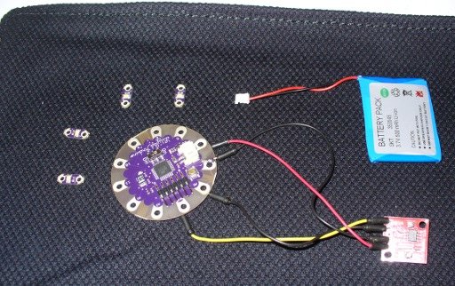
The main circular board in the Arduino-type board which contains an ATmega328 microcontroller, some I/O pins, a header for an FTDI-USB converter and a Li-Ion battery charger/connector. As an aside, this package is good start – as well as the main board you receive the FTDI USB converter, five white LEDs, a buzzer, vibration module, RGB LED, a switch, temperature sensor and light sensor. If you don’t want to invest fully in the LilyPad system until you are confident, there is a smaller E-Sewing kit available with some LEDs, a battery, switch, needle and thread to get started with.
Moving forward – how will the parts be connected? Using thread – conductive thread. For example:
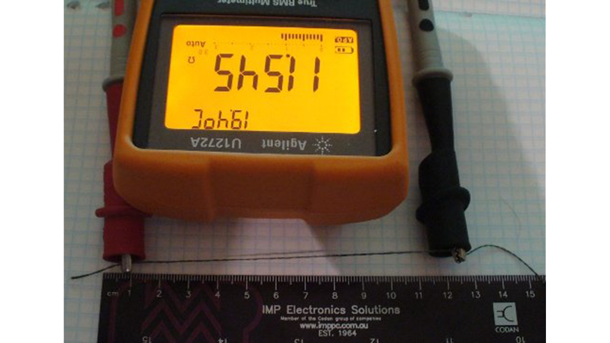
This looks and feels like normal thread, and is used as such. However it is conductive – so it doubles as wire. However the main caveat is the resistance – conductive thread has a much higher resistance than normal hook-up wire. For example, measuring a length of around eleven centimetres has a resistance of around 11Ω:
So don’t go too long with your wire runs otherwise Ohm’s Law will come into play and reduce the available voltage. It is wise to try and minimise the distance between parts otherwise the voltage potential drop may be too much or your digital signals may have issues. Before moving on to the main project it doesn’t hurt to practice sewing a few items together to get the hang of things. For example, run a single LED from a digital output – here I was testing an LED by holding it under the threads:
For more detail: Clock Three – A pillow clock using Arduino