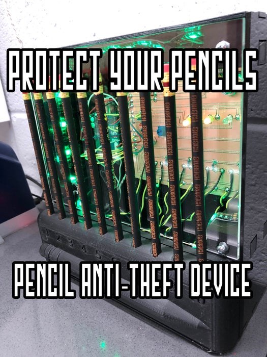
HEY KID, GIVE ME BACK MY PENCIL!
As a teacher, one problem I face every day is losing my pencils. Now pencils don’t just disappear, they walk away in the hands of my middle school students. I know this may not seem like a big deal to you and that’s because it’s really not. But none the less it is a problem I have decided to solve in the most complicated way possible.
This instructable will walk you through how to combine 3D printing, laser cutting, vinyl cutting, printed circuit board milling, wiring, soldering, programming, Arduino, and more to develop an incredibly complex solution to a very minor problem. I created a device that senses when a pencil is taken and automates a sign to flip up. This concept could work for any tool, workshop, organization, or basic security. Through this instructable I will overview how to use Arduino, sensors, and servos with some CNC machines and free software!
Step 1: The Problem
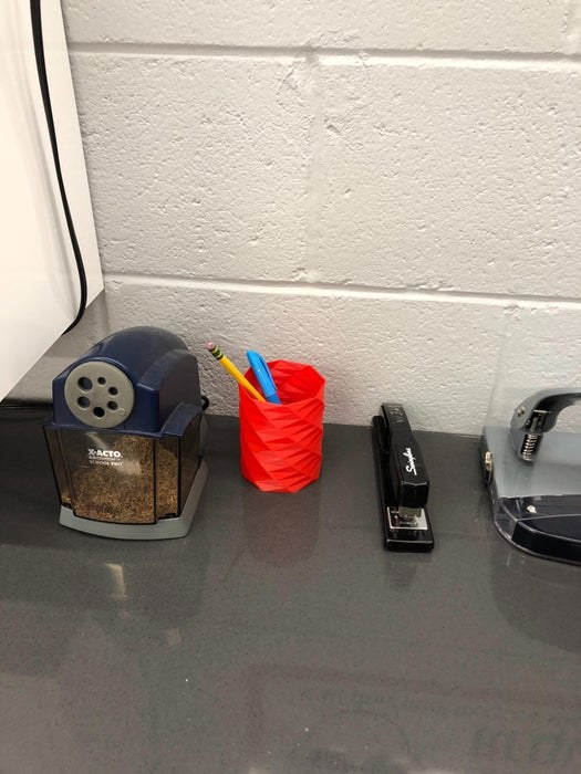
Missing pencils is a problem that many teachers face and they solve it in a variety of ways. A few common solutions are:
- Buying 500 pencils a year
- Write student names on the board
- Taking a shoe as collateral
- Obnoxiously decorating pencils
- Buying golf pencils
Unfortunately none of these solutions worked for me. Instead, I wanted to create a device that would notify me when a pencil was missing. This notification had to be autonomous and obvious. It couldn’t be something that I could miss, nor could it rely on me to input information. I also wanted this device to demonstrate the things that we are learning in our classes. As a technology, engineering, and design teacher, I wanted this device to demonstrate how 3D printers, lasers, mills, graphic design, programming, and electronics all work together to develop a product through the engineering design process.
Step 2: Supplies, Materials, and Tools
My main goal for this project, in addition to protecting my pencils, was to incorporate as many machines and things that we do in class as possible. My students have a good understanding of how the individual machines work, what they make, and so on. However, they often struggle to envision how they can be integrated together to develop a product or system like in industry. I used the following machines to make this device:
- Lulzbot TAZ6 3D printer
- Universal CO2 Laser Cutter/Engraver
- Inventables Carvey CNC Router
- Graphtech CE6000-60 Vinyl Cutter
In addition to these machines, I used a variety of processing equipment and hand tools such as a drill, soldering iron, bandsaw, and so on. For supplies and materials, I used the following for the final product:
- Arduino Uno (1)
- Photo Resistors (10)
- 1k Resistors (8), 470 Ohm Resistor (1)
- 10k Potentiometer (1)
- Assorted LEDs
- 5v RGB LED Light Strip (1)
- Momentary switch (2)
- Toggle Switch (1)
- Continuous Rotation Servo
- Assorted solid-core wire
- Male and Female Plug pigtails
- 9v power adapter
- 22mm Bearing (2)
- Assorted small screws and nuts
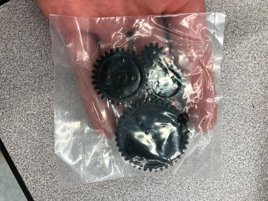
- Assorted plastic gears
- Zip ties
- 1/4″ wooden Dowel
- Solder
- Hot Glue
- PLA 3D printer filament
- 1/8″ clear acrylic
- 1/8″ black acrylic
- 1/4″ Birch plywood
- Foam Core
- Adhesive Vinyl
- 6″x6″ PCB for milling
- PENCILS
Step 3: The Enclosure
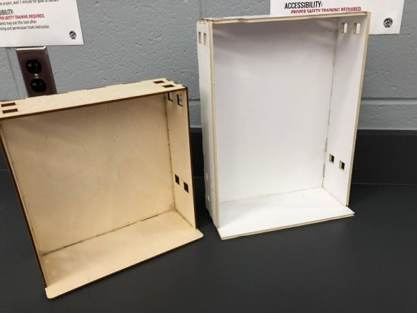
This enclosure combines multiple prototyping machines together. The main box of the enclosure is laser cut out of acrylic and held together using 3D printed corner brackets. It was important that students could see the various components used in this project. To achieve this, I added a clear window to allow for the circuit board and wiring to be visible. I also 3D printed the part of enclosure that held the pencils and light sensors.
For the laser cut part of the enclosure, I designed a box using Adobe Illustrator. You could also use Corel Draw or Gravit designer, or any other vector design program as an alternative. I used Gravit with my middle school students rather than Illustrator because it is simpler, free, and Chromebook compatible. See more about raster and vector design software as well as a bunch of tutorial videos I made in my other instructable here. I cut multiple test boxes out of foam core and plywood to ensure size and fit before making the final box out of acrylic and wasting expensive materials. I have a Universal CO2 laser engraver in my classroom that I used for this project. I personally prefer Universal over other laser engraver brands because of its simplicity, quality, and durability. The software that comes with all Universal is so simple and customizable. I was able to make my own custom material library for my students to choose from specific to my classroom. I can also print right from Illustrator or Gravit without needing to do any additional conversions or steps.
I utilized a 3D printer for the actual pencil holder part, brackets to hold the enclosure together, mounting risers for the PCB and Arduino, and a bracket for the power chord. All of these parts were designed using Onshape, an excellent free and power CAD program that is compatible with mac, windows, chrome books and iPads. I go into detail with different CAD programs and posted a bunch of OnShape and TinkerCAD tutorial videos in my CAD instructable here. For manufacturing these parts, I used PLA filament and a Lulzbot TAZ6 3D printer. PLA is great for general uses and schools because it has minimal fumes and is pretty easy to work with. I am a huge fan of Lulzbot printers. They are versitile, easy to use, extremely durable, and great performance for the price.
For assembly, the laser cut panels fit together pretty well because of the grooves. They are then reinforced by the corner brackets and everything can be held together with a bit of glue. The pencil holder should be glued to the base of the enclosure AFTER THE LIGHT SENSORS ARE INSTALLED (detailed in next step). I also pressed 6-32 nuts into the corner brackets using a soldering iron. PLA softens under heat, simply place the nut over the corner bracket pilot hole and apply pressure using an old soldering iron. The heat will travel through the nut and begin to sink into the printed part, stop pressing once the nut is level with the face of the part. Drill any extra plastic out of the center of the nut using a 1/16″ drill bit.
Step 4: The Wiring & PCB
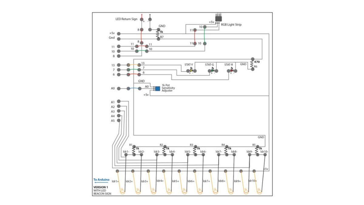
I created a custom Printed Circuit Board (PCB) using an Inventables Carvey CNC Router and their Easel software. The circuit of this device is pretty straight forward. I am using photo resistors to detect whether or not the pencils are in their holders. When a pencil is in the holder, it blocks the light traveling to the photo resistor and the Arduino receives a low value (around 0) through an analog input. When the pencil is out of the holder, light travels into the pencil hole and the Arduino receives a higher signal (around 50). These signals will vary based upon the photo resistors you use, the way you connect them, and the amount of light in your room.
I used 10 photo resistors that were hot glued into the back of my 3D printed pencil holder. All of the photo resisters were wired as pull-down resistors using a 1K resister for each. A pull-down configuration allows for a 0 to be sent when there is no value in order to void invalid readings and floating voltages. This is incredibly important with digital electronics and inputs, I used the same configuration later for momentary switches. I also used an Arduino uno for this project which only has six analog inputs. Ideally, each photo resistor would have its own input so you can individually monitor and control the values. Because I only had 5 inputs to work with (input 0 was used by the POT) I doubled up the sensors. I paired 1&2, 3&4, 5&6, 7&8, and 9&10. By combining sensors into a single input I lost some control with calibration, rather than being able to tweak individual sensors or troubleshoot individual sensors I had to troubleshoot in pairs. Technically you could chain them all into a single input but you would loose even more calibration control and your value range would decrease. I get into greater detail about calibrating and reading sensor values in the calibration step of this Instructable. Analog input 0 is connected to a potentiometer that I used to adjust the threshold based upon the brightness of the room. Again, I will get into greater detail about this during the calibration step.
The system has an RGB light strip in the main enclosure that is green when pencils are in and red when at least one is missing. I purchased a 5v RGB light strip and cut the blue channel off because I was only using red and green for this project. In addition to the light strip I added a few status lights on my PCB, yellow for main power, green for pencils in, red for pencils out. I used a 470 ohm resistor on the ground channel of all three status LEDs.
The last main part of the circuit is the beacon. I ended up redesigning this part of the project three times and I get into greater detail about each attempt in the next step. My original idea was to have a huge laser etched acrylic sign with red LEDs that only turned on when a pencil was missing. In the circuit, I simply sent a digital output from pin 8 to the sign to turn it on or off. I ended up switching to a servo operated sign in the next step, but the PCB was not changed.
I am no expert in PCB design or milling by any means. A PCB should really be designed in Autodesk Eagle or another specialized program. All of these programs are out of my wheelhouse (for now) and because this circuit was pretty simple I was able to draw a vector design in Adobe Illustrator, then export it as an SVG and upload it to Easel, Inventables’ Milling application. I took a while for me to get the circuit board to come out as I wanted but in general Easel is incredibly straight forward. PCB is an material option in the materials menu but I was surprised that PCB bits were not a default option even though I was using the official Inventables PCB bit pack. Inventables support told me to use a square bit set to 0.020″ which worked pretty well. When designing a PCB in Illustrator, it took some experimenting to get the Carvey to mill it in one pass with out destroying the channels. You can’t directly control the number of passes in Easel, it is automatically determined based upon the bit diameter and depth of cutting, and cutting pattern. My PCB design had a 2pt stroke weight and I exported it as an expanded path merged with my mounting circles. I then used Easel’s outline function to carve around my exported path rather than exporting an outline from illustrator. Once I set the material thickness to 0.014″, Feed to 10 in/min, Plunge to 9 in/min, and depth per pass to 0.005″in, it only took about 15 min for the whole PCB. I then used a 0.010″ PCB bit to mill the holes as a separate job. I used the same settings except my depth per pass was now 0.06″ to plunge through.
After milling the PCB, trim away any excess material if you plan to use my enclosure file. Its a tight fit with the corner brackets and I did NOT test fit until AFTER I soldered. It was not a fun experience cutting the PCB down with all the components attached. For the soldering, I intentionally soldered the PCB upside-down. Yes, you read that correctly. You’re supposed to push your components through so the copper is on the bottom, allowing for you to easily solder your component leads. I intentionally did the opposite, mounting my components to the bottom copper side of the PCB so that my students could view the milled channels through the enclosure. This wasn’t too challenging, but certainly not what the PCB was intended for. If you plan to do this, do not push your components all the way though the PCB and leave some room to fit the soldering iron below them. This was pretty easy with LEDs and resistors, not so much with the potentiometer. Be careful not to make direct contact with the PCB for more than a few seconds to avoid melting off a channel and some copper.
Step 5: The Beacon
The beacon was really the main contender for the real-world functionality of the device. Remember, the problem was that I am losing pencils and I cannot remember when they are borrowed or who borrows them. The beacon was supposed to be this giant bat-signal like device that made it obvious that a pencil was borrowed. I would not dismiss until all pencils are returned, like I do for my other tools, chairs, etc. In total, I went through three different beacon versions.
Version 1, the version described in the previous step regarding the PCB and circuit design, was the simplest and may work for you. The idea was like the bat-signal, a giant and bright illuminated sign. I laser cut a 1/4″ sheet of acrylic and wired 30 super bright LEDs into a 3D printed sign holder. After connecting to a power supply it became apparent that 30 super bright LEDs were far from enough so I drilled more holes and added 15 more LEDs. Still no good. My room has LED lights and it is just too bright to obviously notice that the sign was illuminated. I sanded the edges of the acrylic to attempt to trap the light more and even played around with another RGB LED strip. I think the only way to make it brighter would have been to put LEDs all the way around and that was something I did not want to do.
So I redesigned. Version 2 and 3 use a servo motor to flip up a sign when at least one pencil is removed. Version 2 was far from my best work and as a result failed pretty miserably. I laser cut a piece of red 1/8″ acrylic and put a white vinyl sticker on it. I then used some really crude 3D printed brackets to attach it directly to a servo motor. Shockingly, the servo motor was not strong enough to flip the sign up, nor was anything balanced or straight and square.
Version 3 was much better and is still working out pretty well. Step one for version 3 was to make the sign lighter so I used foam core with a vinyl sticker instead of acrylic. Step two was to reduce the amount of work on the servo. Do do this, I mounted the sign to an axel made from a 1/4″ wooden dowel that sat in two 22mm bearings with 3D printed spacers (1/4″ to 8mm for the inside diameter of the bearings). Lastly, I drilled out some basic plastic gears from a random kit so a smaller 1″ gear was attached to the servo and a 3″ gear was attached to the wooden dowel axel.
After some testing, I found that it was challenging to make the sign stop exactly where I wanted it to even with the gears. I believed that if a student played with it my positions could be thrown off and it would never be quite right. To solve this, I added two momentary switches wired in a pull-down configuration with 1K resistors. One switch identified when the sign flipped all the way down to stop the servo from rotating counter clockwise, the other for when the sign flipped up to the desired position. As with any good middle school project, everything was held together with a gallon of hot glue and zip ties.
I did not redesign the PCB (yet) for the updated beacon signs with servos. Instead, I wired the servo to the original LED sign pin 8 and ground on the top left of the PCB after desoldering resistor #7 and replacing it with a jumper wire. I then pulled a connection directly from the Arduino for +5v, pin 1 for switch 1, and pin 2 for switch 2. All of these wires go through long leads up to a mini breadboard mounted to the sign base. See the updated schematic image above for more details about the new wiring configuration.
Step 6: Assembly
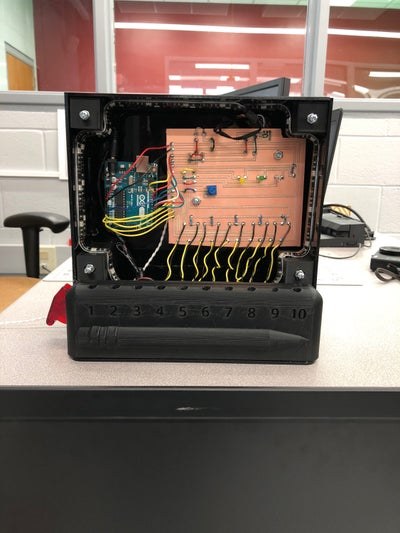
After assembling the enclosure with the corner brackets as described in the enclosure step, you are ready for the main component installation. I 3D printed some riser rings to lift the Arduino and PCB off the back of the enclosure. Rather than milling or laser cutting mounting holes during manufacturing, I decided to manually drill holes during assembly because I was uncertain as to how everything would fit. Also, remember to trim the PCB before soldering (unlike me) as I described in the circuit step. I used two 6-32 bolts for the Arduino, and three for the PCB. I then used A LOT of hot glue to attach the 3D printed pencil holder to the base along with some sheet metal screws for good luck.
To turn the device on and off, I purchased a automotive racing switch (just ’cause) and wired it to cut off power between my 9v adapter and the M/F plug ends going to the Arduino power-in. I also cut off the tab of the switch cover so it could be installed upside down (see images). Now the switch will be covered when it is ON during the day and the cover needs to be lifted to power it OFF. I thought that would better prevent my students from playing with it during the day.
Do not attach the clear acyclic front window until after calibration. Determine where you want the holder to be and mount it before calibrating. I spent about 20 minutes calibrating, then moved the enclosure to put the window on and could not put it back in the EXACT same spot so all of my calibration and values were wasted the first time around.
Source: Classroom Pencil Protection Machine