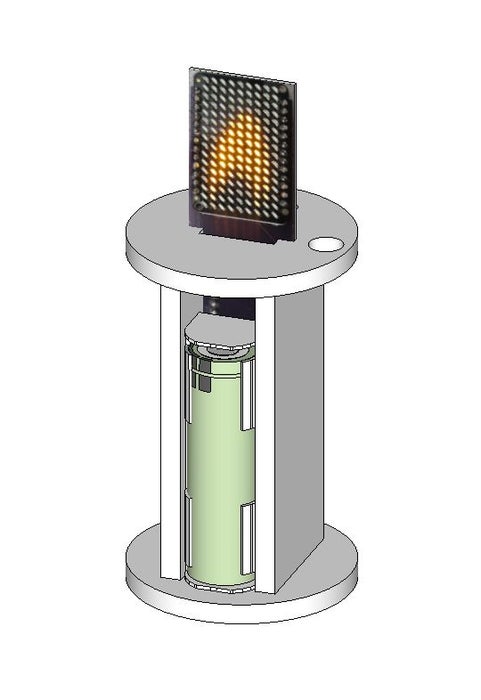
Three years ago I saw “My New Flame” by MORITZ WALDEMEYER, INGO MAURER UND TEAM 2012 at the museum gift shop, and feel in love with the idea. I hoped to recreate something mesmerizing, enjoyable, functional and interesting to watch, but with a slight twist. I certainly couldn’t make anything comparable to the their beautiful work of art. Therefore, I created a Clapper version of an LED Candle. Clap twice to turn the candle ON or OFF. The Clapper feature is optional, and can be turned ON or OFF if included in the build. Or, this feature may be omitted from the build entirely.
There are seven of these around my house which I use as ornamental candles and night lights. I keep them plugged into a 5 VDC Cell Phone Charger to power the unit, and to recharge the Li-Ion battery. One charge can last around 18 hours, which makes them great for emergency lighting.
Note: The Candle in the video on the right side with a cover isn’t a Clapper Candle.
Step 1: Parts and Tools
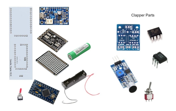
Parts Needed for Project:
- 1 ea Lumiere Candles Smooth Resin Candle – 6″ H x 3″ OD
- 1 ea Arduino Pro Mini Board ATMEGA328P 16MHz 5V
- 1 ea LED Charlieplexed Matrix – 9×16 LEDs – Yellow [ID:2948]
- 1 ea Adafruit 16×9 Charlieplexed PWM LED Matrix Driver – IS31FL3731 [ID:2946]
- 1 ea Adafruit PowerBoost 500 Charger
- 1 ea 18650 Li-Ion Battery
- 1 ea 18650 Battery Holder
- 1 ea SPST Toggle Switch
- 1 ea Custom Printed Circuit Board
- Clear Acrylic Plastic 6mm
With Clapper (Optional):
- 1 ea ATMEL / Microchip Technology DIP-8 ATTINY85-20PU
- 1 ea DIP-8 socket
- 1 ea LCB710 Solid State Relay
- 1 ea High Sensitivity Sound Detection Module
- 1 ea 220 Resistor
- 1 ea Sub-Miniature Toggle Switch 2MS1T1B1M2QES ON/ON 3P-SPDT
- 1 ea Custom Printed Circuit Board
Tools:
- 1 ea CP2102 Micro USB To UART TTL Module 6 Pin – ebay.com
- Soldering Iron
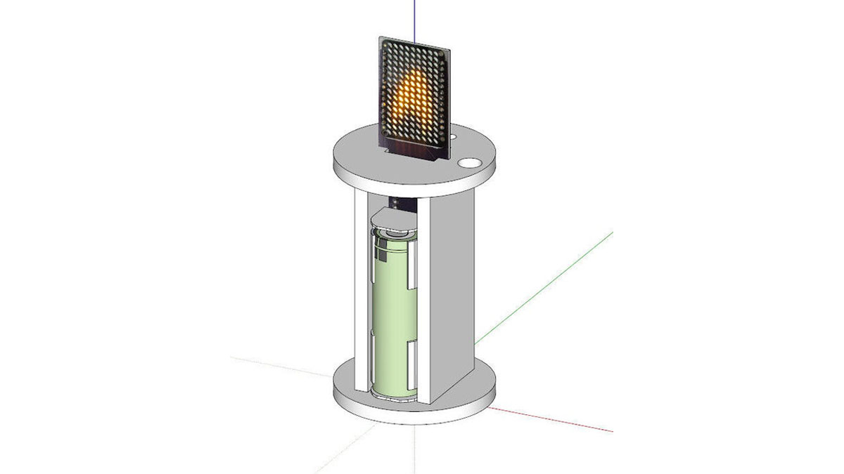
Step 2: Acrylic Base Assembly
Using the PDF Vector drawings supplied, the tool paths for cutting out the acrylic can be created. Each PDF file contains Top, Bottom, two Sides and a small rectangle that is used as a spacer underneath the Sound Module. This part is not needed if you’re building the non-Clapper (without Sound) version of this LED Candle.
I used a 1/8″ end mill to cut the majority of the parts, and I ran a finishing pass with a 1/16″ end mill. The 1/16″ end mill is required for the narrow slots on the sides and top.
The mounting holes were manually located and drilled by hand. Some of the holes should be drilled prior to assembly. For example, the holes to mount the PowerBoost board.
Sand and test fit the all the pieces. I recommend using Plast-I-Weld to bond the pieces together.
Note: The diameter of the top and bottom must be sized to the inside diameter (ID) of the resin candle bodies you purchase.
Step 3: Circuitry With and Without Clapper
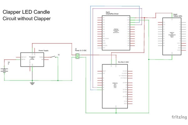
The basic LED Candle circuitry consist of a battery, switch, power supply and Candle Printed Circuit Board (PCB) with a LED Charlieplexed Matrix, Charlieplexed Matrix Driver and Arduino Pro Mini 5 VDC. An assembled version of the Candle Circuit Board can be seen above. The only connection to this PCB is 5 VDC provided by the power supply. The battery is connected to the PowerBoost power supply, which can charge the Li-Ion battery, and provide protection for a low voltage battery. The power supply also provides a means of switching the Candle ON or OFF by grounding the EN connection via the switch.
The Clapper PCB includes a solid state relay (LCB710) and microcontroller (ATTiny85) to process the signals from the Sound Module and control the power to the Candle PCB. The ATTiny85 is programmed to listen for two loud simultaneous sounds, and toggle the relay ON or OFF. Unfortunately, this configuration cannot distinguish a clap from any other loud sounds, therefore, the circuit will activate if any two loud sounds are heard simultaneously.
I installed a DIP-8 socket on the Clapper PCB to make it easy to install or remove the ATTiny85. All other components can be soldered to the board.
Connect pins 1&2 of J1 for normal operation. Secondly, connect the + & – pins of the Clapper PCB to the + & – of the Candle PCB. Connect the 5V & GND of the PowerBoost power supply to the + & – of “PWR IN” connections of the Clapper PCB. Connect the Mini Toggle Switch SPDT to the “CLAPPER” connection. Connect the pole of the switch to C and the other two connections as desired. Finally, connect the VCC and GND of the Sound Module to the + & – of “SND MOD”, and the OUT to the Out connection of the Clapper PCB.
Source: Clapper LED Candle