Summary of Circuit provides constant-current load for testing batteries
This article describes a constant-current load circuit for testing AA and AAA alkaline batteries, recommending a 250 mA test current over simple short-circuit or open-circuit methods. The device uses a 9V battery and voltage regulator to generate 5V, driving transistors and op-amps to sink a precise current independent of the battery's output voltage. LEDs provide visual feedback on battery health based on voltage thresholds under load.
Parts used in the Battery Tester:
- 6Ω resistive load
- 9V battery
- Voltage regulator
- IC1
- IC2 (Operational Amplifier)
- Q3 (Transistor)
- R19
- R18
- R4
- Q2 (Transistor)
- Q1 (Transistor)
- D3 (LED)
- D4 (LED)
- D5 (LED)
- D6 (LED)
- R14
Suppose that you need to test a 1.5V, AA-size alkaline battery. You can apply a short circuit and measure current, or you can measure open-circuit voltage, but neither method properly tests the battery. A suitable test current of approximately 250 mA gives you a more reasonable test. You can use a 6Ω resistive load at 1.5V, which produces an output voltage of 1.46V at an ambient temperature of 25°C if the battery is in excellent condition. A poor battery might produce less than 1.2V. Given the load, the output current at 1.2V will be 200 mA instead of 250 mA. The battery will have just 80% of a full load current. Instead, you can use the circuit in Figure 1 to produce a constant-current load.
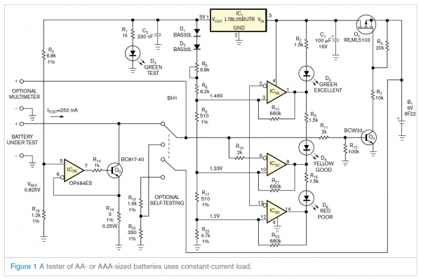
The circuit uses a 9V battery and a voltage regulator to produce a steady power-supply voltage of 5V. From that voltage, the circuit produces a constant sink current, which is independent of the battery’s output voltage, using IC1, IC2, and Q3. Your choice of current depends on battery size. You calculate the sink current of this circuit as ITEST=1/R19×[VCC×R18/(R4+R18)], where ITEST is the current you are testing and VCC is the voltage of resistive divider R4 and R18. The voltage across R19 should range from 0.3 to 0.85V for AAA and AA batteries. Transistor Q3 should be in its active region. Resistor R14 limits Q3’s base current to a safe level.
A suitable choice for the operational amplifier, IC2, is also important. You should use a single-supply op amp with a rail-to-rail input and a rail-to-rail output, such as Analog Devices’ OP484ES or OP496GS.
When you connect the battery under test, Q2 turns on, which then turns on Q1, applying voltage from the 9V battery to the regulator. That action lights D3, indicating that the battery under test has enough voltage to be tested. LEDs D4, D5, and D6 indicate the battery’s condition. Table 1 shows the voltage ranges necessary for these LEDs to light.
For More Details:Circuit provides constant-current load for testing batteries
- Why is measuring open-circuit voltage insufficient?
Neither short-circuit nor open-circuit voltage measurements properly test the battery. - What is the recommended test current for an AA battery?
A suitable test current is approximately 250 mA. - What voltage indicates an excellent condition AA battery under load?
An output voltage of 1.46V at 25°C indicates excellent condition. - How does a poor battery affect the output current?
A poor battery producing less than 1.2V results in 200 mA instead of 250 mA. - What formula calculates the sink current ITEST?
The formula is ITEST=1/R19×[VCC×R18/(R4+R18)]. - Which operational amplifiers are suitable for IC2?
Single-supply rail-to-rail op amps like OP484ES or OP496GS are suitable. - What function does LED D3 serve?
LED D3 lights up to indicate that the battery under test has enough voltage to be tested. - What role does resistor R14 play in the circuit?
Resistor R14 limits Q3’s base current to a safe level. - What is the required voltage range across R19 for testing?
The voltage across R19 should range from 0.3 to 0.85V for AAA and AA batteries. - What happens when you connect the battery under test?
Q2 turns on, which then turns on Q1, applying voltage from the 9V battery to the regulator.