Summary of Build Your Own Digital Weighing Machine
This article details the construction of a low-cost, 5kg digital kitchen weighing machine using an ATmega328 microcontroller and HX711 amplifier. It covers circuit design, software calibration via Arduino IDE, and assembly instructions. The device features self-calibration with zero-setting stored in EEPROM for consistent accuracy across power cycles.
Parts used in Digital Kitchen Weighing Machine:
- 5V voltage regulator 7805 (IC1)
- Analogue amplifier HX711 (IC2)
- ATmega328 microcontroller (IC3)
- Load cell (strain gauge) up to 5kg
- Discrete components
- Male bergstrip connectors
- Push button S1
- LCD1 display
- Suitable enclosure box

This article describes how to build a simple and low-cost digital kitchen weighing machine, which can measure weight of up to five kilograms. This digital weighing machine is easier to design. For a heavy-duty weighing machine like your bathroom scale, just change the load cell or strain gauge. Everything else remains the same.
Circuit and working
Circuit diagram of the weighing machine is shown in Fig. 2. It is built around 5V voltage regulator 7805 (IC1), analogue amplifier HX711 (IC2), ATmega328 microcontroller (IC3), load cell (strain gauge) for up to 5kg and a few discrete components. The author’s prototype is shown in Fig. 1.
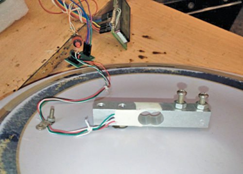
Author’s prototype
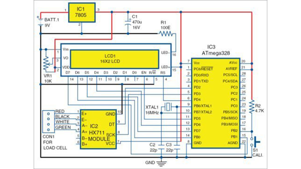
Circuit diagram of weighing machine
HX711 is used here because it gives a digital output, is low-cost and has an Adafruit header file for Arduino, which makes it easy to use. HX711 has input channel A (A+ and A-) and channel B (B+ and B-). Here, channel B is left unused. If you want to add one more load cell to take average, you can connect it to channels B- and B+. HX711, along with male bergstrip connectors, as shown in Fig. 3.
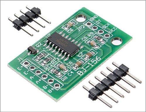
Analogue amplifier HX711
Load cell. Details of the load cell are shown in Fig. 4. The weighing scale has a metallic structure surrounded by strain-relieving frames, which pick up the strain when subjected to weight. Strain gauges are arranged in Wheatstone bridge configuration. Voltage is applied on one side, while the other side measures the change in voltage depending on the strain it suffers.
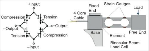
Load cell
Load or weight is applied at the free end. Strain gauges are applied on all three sides to pick up compressions and expansions. These are nothing but load signals that are processed and measured for weight measurements. Output is clubbed into four wires. Functions of the colour codes of the four wires are given in the table.
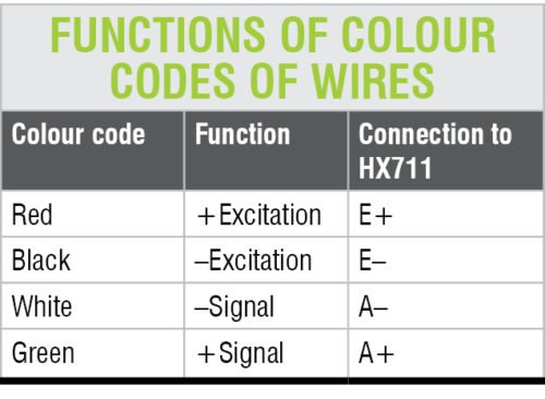
function of color codes of wires
A yellow wire, if present, is the shield wire that must be connected to ground.
Software
The software consists of Arduino sketch (my_load_cell.ino), HX711 header files and other related libraries. First, add the library files (floatToString, HX711 and writeAnything) to Arduino IDE library and then run the sketch. To calibrate the probe, press the push button once. To reduce the number of readings for averaging, change the following script:
x=scale.get_units(25)×45.3592 ; //convert to gram for 25 readings
scale.read_average(5); //to read 5 average
The first line takes 25 readings and averages it five times using the second line of code. To increase the speed of reading, reduce the number of averages. If input is blank, it will not take any average.
Software is built on Arduino onboard principle. After uploading the code into ATmega328 using Arduino Uno, take ATmega328 IC out and put into the PCB board.
Initial readings may have errors, as the system is not yet calibrated. Press push button S1 connected to pin 16 (PB2) of IC3 once and the system will self-calibrate. Initial reading of 0.0 will be shown on LCD1. The zero_set figure will then be stashed into the inbuilt EEPROM of Arduino.
Next time when you restart it after switch off operation, zero_set reading will be read from the EEPROM and internal calibration will be adjusted accordingly. It will be shown on the top line of LCD1. The second line will show 0.0.
If the readings reduce with increase in load, reverse the white and green wires, and the problem will be solved.
Download source file
Construction and testing of Digital Weighing Machine
An actual-size PCB layout for the weighing machine is shown in Fig. 5 and its components layout in Fig. 6. After assembling the circuit, enclose it in a suitable box. Attach one end of the load cell in a fixed frame. The other end should be used for placing the load or object for weight measurement.
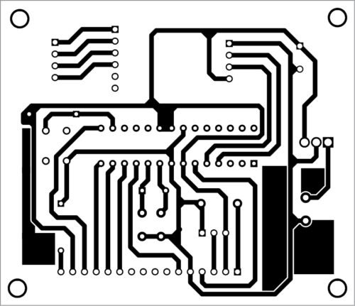
PCB layout of the weighing machine circuit
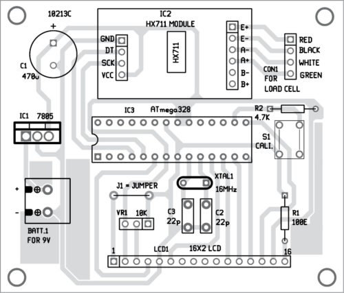
Component Layout of the PCB design
Calibration
Calibration is an important part of measuring devices. For HX711 there is one calibration factor 7050 that works well for Adafruit modules. Therefore it has not been changed. The other is zero_set factor for which provision should be made to do it dynamically during operations. After each calibration, zero_set figure goes into EEPROM memory of Arduino. Next time when you restart the circuit, this value will be fetched from EEPROM and zero_set achieved.
Read More detail :Build Your Own Digital Weighing Machine
- How do I calibrate the probe?
Press the push button once to start the self-calibration process. - Can I add another load cell to average readings?
Yes, you can connect a second load cell to channels B- and B+ on the HX711. - What is the function of the yellow wire?
The yellow wire is the shield wire that must be connected to ground. - How does the system handle zero readings after restart?
The zero_set figure is stashed into the EEPROM and fetched automatically upon restart. - What should I do if readings reduce when load increases?
Reverse the white and green wires to solve the problem. - How can I increase the reading speed?
Reduce the number of averages in the script code. - Which library files are required for the software?
You need floatToString, HX711, and writeAnything libraries. - Does this project work for heavy-duty scales like bathroom scales?
Yes, by changing the load cell or strain gauge while keeping other components the same.