Summary of Build Your Own Programmable LED Matrix
This article details the assembly of a large, programmable LED matrix capable of displaying QR codes. It guides users through soldering components onto control and matrix PCBs, including resistors, capacitors, transistors, and LEDs. The project utilizes an Arduino-compatible setup with the LEDcontrol library to customize the display.
Parts used in the Programmable LED Matrix:
- Soldering iron and solder
- LEDcontrol library
- LEDs (10mm recommended)
- Wire cutters and strippers
- Jumper wire
- LED Matrix PCB
- 47 Ω resistors
- 10μF capacitor
- Control Board PCB
- 150k Ω resistor
- 0.1μF capacitor
- IRF9Z34N transistors
- IC socket
- Pan head screw, 4-40x3/8"L
- 2N2222A transistors
- 2x8 female header
- Hex spacer, 4-40x7/40"L
- 1k Ω resistors
- 2x8 male header
- Hex standoff, 4/40x3/8"
- 1.5k Ω resistors
- MAX7219 IC
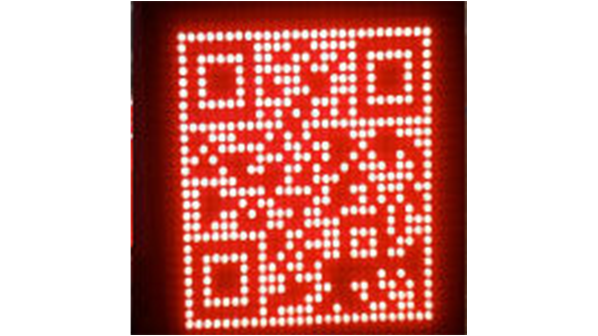
QR codes are addicting. Smartphones are smart enough to read them from virtually any angle or orientation. But imagine taking it a step further. I had dreams of a digital LED array that I could program with QR codes, and I wanted it really big!
I used 16 matrices to create the QR code that is pictured here. You may purchase the kit to build an 8×8 panel from Jameco.
LEDs are not included to give you the freedom to choose your own size and color.
Step 1: Requires
Soldering iron and solder
LEDcontrol library
LEDs (10mm recommended)
Wire cutters and strippers
Jumper wire
LED Matrix Kit Includes:
LED Matrix PCB
47 Ω resistors
10μF capacitor
Control Board PCB
150k Ω resistor
0.1μF capacitor
IRF9Z34N transistors
IC socket
Pan head screw, 4-40×3/8″L
2N2222A transistors
2×8 female header
Hex spacer, 4-40×7/16″L
1k Ω resistors
2×8 male header
Hex standoff, 4/40×3/8″
1.5k Ω resistors
MAX7219 IC
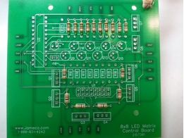
Step 2: Install Pin Headers
Temporarily install a few spacers on the control board and stand the board pair on one side so both boards are square to each other. Tighten the spacers. This has an added benefit if you are building multiple matrices. They will all sit nicely flush next to one another.
Step 3: Install the Resistors
R1 – R8 = 1k Ω (brown-black-red)
R9 – R16 = 47 Ω (yellow-violet-black)
R17 – R24 = 1.5k Ω (brown-green-red)
R25 = 150k Ω (brown-green-yellow)
Step 4: Install the Capacitors
C1 = 10μF electrolytic capacitor and is polarized. Note the stripe indicating the negative side. The silkscreen shows a “+” sign for positive. Solder the capacitor with enough space that you can bend the capacitor over to lay flush with the board.
Step 5: Install Transistors
Q9 – Q16 = 2N2222A. Make sure each transistor says 2N2222A. (If it’s something else, it could cause the opposite action to happen once programmed.
Helpful Tip: Solder one lead of each transistor at a time. This holds them in place and allows you to make minor adjustments. It also allows the transistors a brief period to cool before you solder the next lead.
Q1 – Q8 = IRF9Z34N. These transistors must be placed in the correct orientation. The sliver of a rectangle on the silkscreen indicates the backside of the transistor. Bend the leads back 90 degrees so the transistors will lay flat on the PCB when installed. You may also choose to leave a slight gap between the back of the transistor and the PCB for airflow to keep components cool.
Step 6: Install Socket and ICs
Step 7: Install the LEDs
Step 8: Install the Spacers and Standoffs
Step 9: Complete Wiring
- What is the purpose of the 10μF capacitor?
C1 is a polarized electrolytic capacitor that must be positioned correctly according to the silkscreen markings for the circuit to work. - How should the IRF9Z34N transistors be oriented?
The sliver of a rectangle on the silkscreen indicates the backside, and leads should be bent back 90 degrees so they lay flat on the PCB. - Which leg of the LED indicates the negative side?
The shorter leg of an LED is negative, and the flat side of the LED on the silkscreen also indicates the negative side. - Can I choose my own LED size and color?
Yes, LEDs are not included in the kit to give you the freedom to choose your own size and color. - Why should I solder one lead of each transistor at a time?
This holds them in place allowing for minor adjustments and gives the transistors a brief period to cool before soldering the next lead. - How do I secure the two PCB boards together?
Line up the pins of the headers and press the boards together, then use pan head screws to secure both modules. - What is the function of the spacers and standoffs?
Spacers go between the control board and matrix board, while standoffs thread into the spacers from the underside of the control board to hold them apart. - Does the MAX7219 IC require specific orientation during installation?
Yes, you must note the notch on the end near pin 1 when installing the Max7219 IC into the socket.